Hydraulic composite molding and hydraulic molded products

a composite molding and hydraulic technology, applied in the field of composite molding processes and composite molded products, can solve the problems of low application value, low cost of such prior art structural members, and relatively labor-intensive and expensive fabrication processes they displaced

Inactive Publication Date: 2005-03-10
DANZIK DENNIS M
View PDF11 Cites 27 Cited by
  • Summary
  • Abstract
  • Description
  • Claims
  • Application Information

AI Technical Summary

Problems solved by technology

While these processes are labor intensive, and thus relatively expensive, the fabrication processes they displaced were also relatively labor intensive and expensive, with the superior properties of the composite molded product usually dictating its use.
In other applications such as in certain structural members, including columns, beams and utility poles, and in more complex structures, composite molded structures are not yet frequently used because of their cost.
Such structural members can offer many advantages over steel, concrete and wood, though the cost of such prior art structural members has limited their application.
However, cost remains an impediment to their more widespread use.

Method used


Image

  • Hydraulic composite molding and hydraulic molded products
  • Hydraulic composite molding and hydraulic molded products
  • Hydraulic composite molding and hydraulic molded products

Examples


Embodiment Construction

[0023] In the following description of preferred methods of practicing the present invention, a basic process or method will be described, together with exemplary equipment for practicing the method and for the manufacture of specific types of products, after which exemplary variations and improvements will be described for the manufacture of the same or similar products. Thereafter, the method will be described with respect to manufacture of exemplary products of substantially different characteristics and configurations.

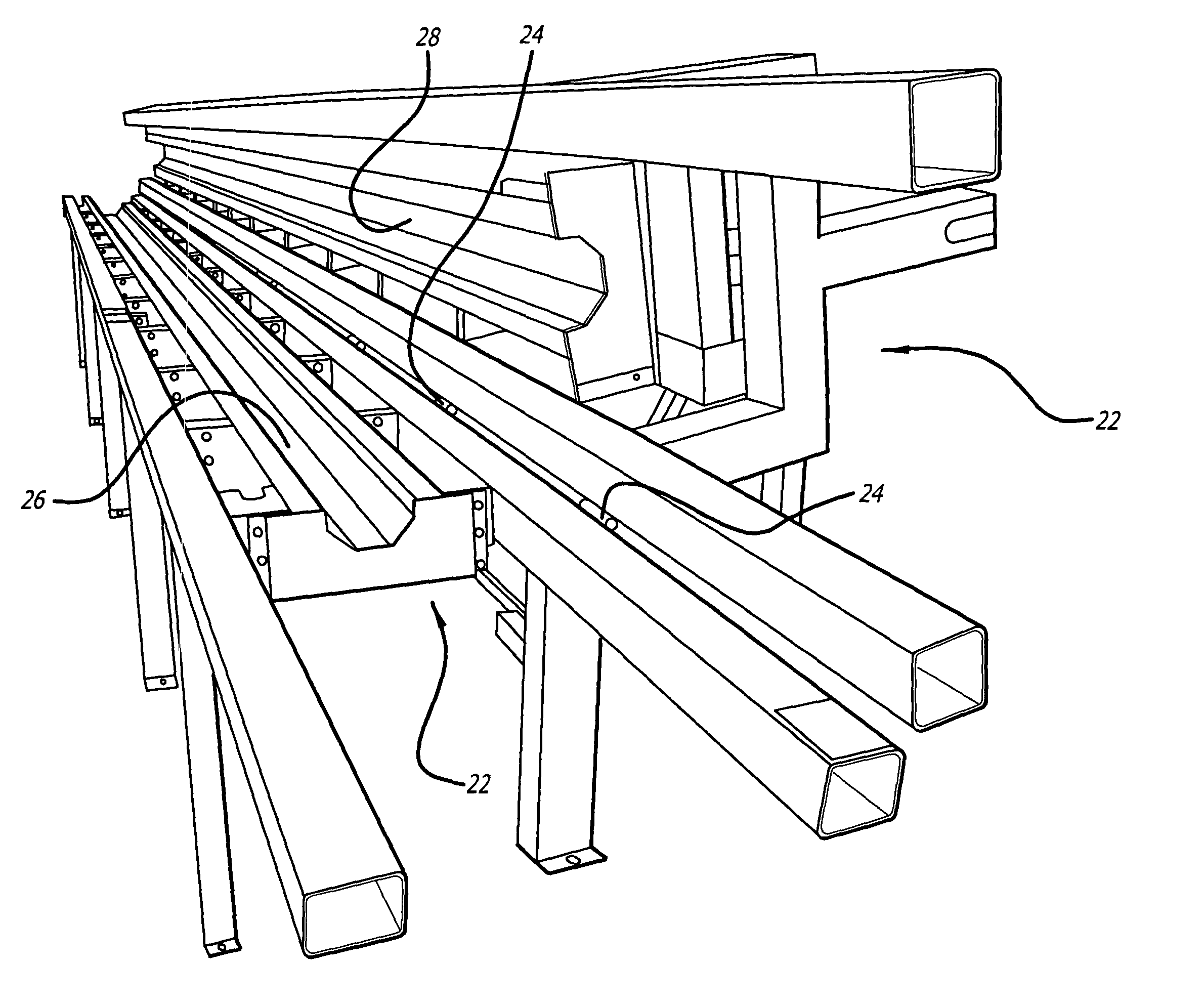
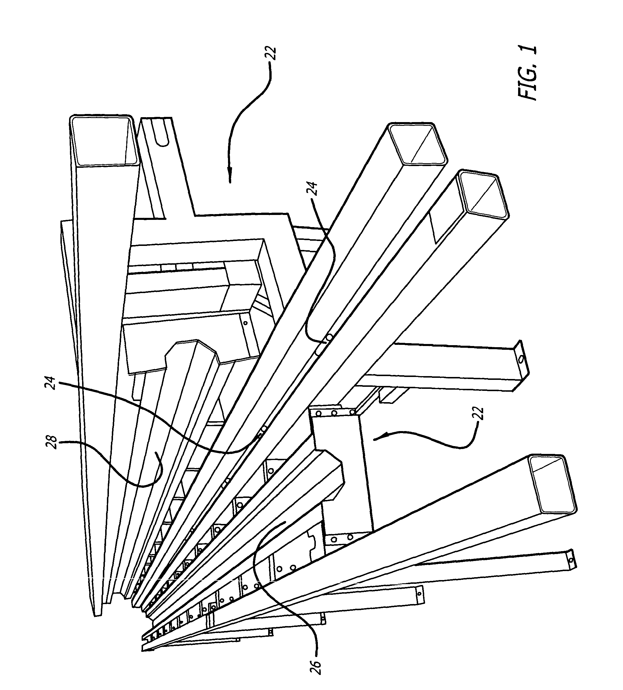
[0024] Referring now to FIG. 1, an exemplary mold suitable for fabricating poles such as utility poles, and columns and beams for buildings and the like, may be seen. In the particular mold shown, two mold halves, generally indicated by the numerals 20 and 22, may be seen. These mold assemblies are hinged together along one side thereof by hinges 24 so as to be openable, as shown in FIG. 1, and closable, as shown in some of the later Figures to be described. Each ...


PUM

PropertyMeasurementUnit
lengthaaaaaaaaaa
pressureaaaaaaaaaa
structuresaaaaaaaaaa

Abstract

Composite hydraulic molding that results in low cost, lightweight and strong composite structures. In accordance with the process, reinforcing material, which may be a mat and / or fabric of high strength filament, is placed in a mold, an inflatable tube 34 is placed over the reinforcing material and further reinforcing material, which may be integral with the reinforcing material under the inflatable tube, is placed over the inflatable tube. The mold is closed, and a thermosetting resin is pumped into the mold. The inflatable tube 34 is then inflated with a liquid, saturating the reinforcing material and forcing any air in the mold out of one or more bleeder holes in the mold. After curing the resin, the inflatable tube 34 is deflated and removed and the mold opened to remove the molded part. Various embodiments and additional features are disclosed.

Description

BACKGROUND OF THE INVENTION [0001] 1. Field of the Invention [0002] The present invention relates to the field of composite molding processes and composite molded products. [0003] 2. Prior Art [0004] Composite molding processes and composite molded products are well known in the prior art, and in some applications have substantially displaced prior fabrication techniques and materials because of their many superior properties compared to prior art materials. By way of example, most new pleasure boats are made of fiber reinforced resins using hand lay-up molding processes. While these processes are labor intensive, and thus relatively expensive, the fabrication processes they displaced were also relatively labor intensive and expensive, with the superior properties of the composite molded product usually dictating its use. [0005] In other applications such as in certain structural members, including columns, beams and utility poles, and in more complex structures, composite molded st...

Claims


Application Information

Patent Timeline
Patent Type & Authority Applications(United States)
IPC IPC(8): B29C33/26B29C70/44
CPCB29C33/26B29L2031/766B29C70/446
Inventor DANZIK, DENNIS M.
Owner DANZIK DENNIS M
Why Eureka
Try Eureka