System for time thresholding

a time thresholding and system technology, applied in the field of signal processing, can solve the problems of system inability to make the determination, channel unusable, valuable time loss,

Inactive Publication Date: 2005-03-10
LOCKHEED MARTIN CORP
View PDF27 Cites 12 Cited by
  • Summary
  • Abstract
  • Description
  • Claims
  • Application Information

AI Technical Summary

Problems solved by technology

However, radio frequency interference may corrupt the channel and make the channel unusable.
However, if the next channel is also corrupted with RFI, the system cannot make the determination until the completion of the next dwell.
If several corrupted channels are assigned to the system in sequence, valuable time is lost.
This imposes computational and throughput burdens on a receiver system and may slow signal intercept performance in the presence of RFI.

Method used


Image

  • System for time thresholding
  • System for time thresholding
  • System for time thresholding

Examples


Embodiment Construction

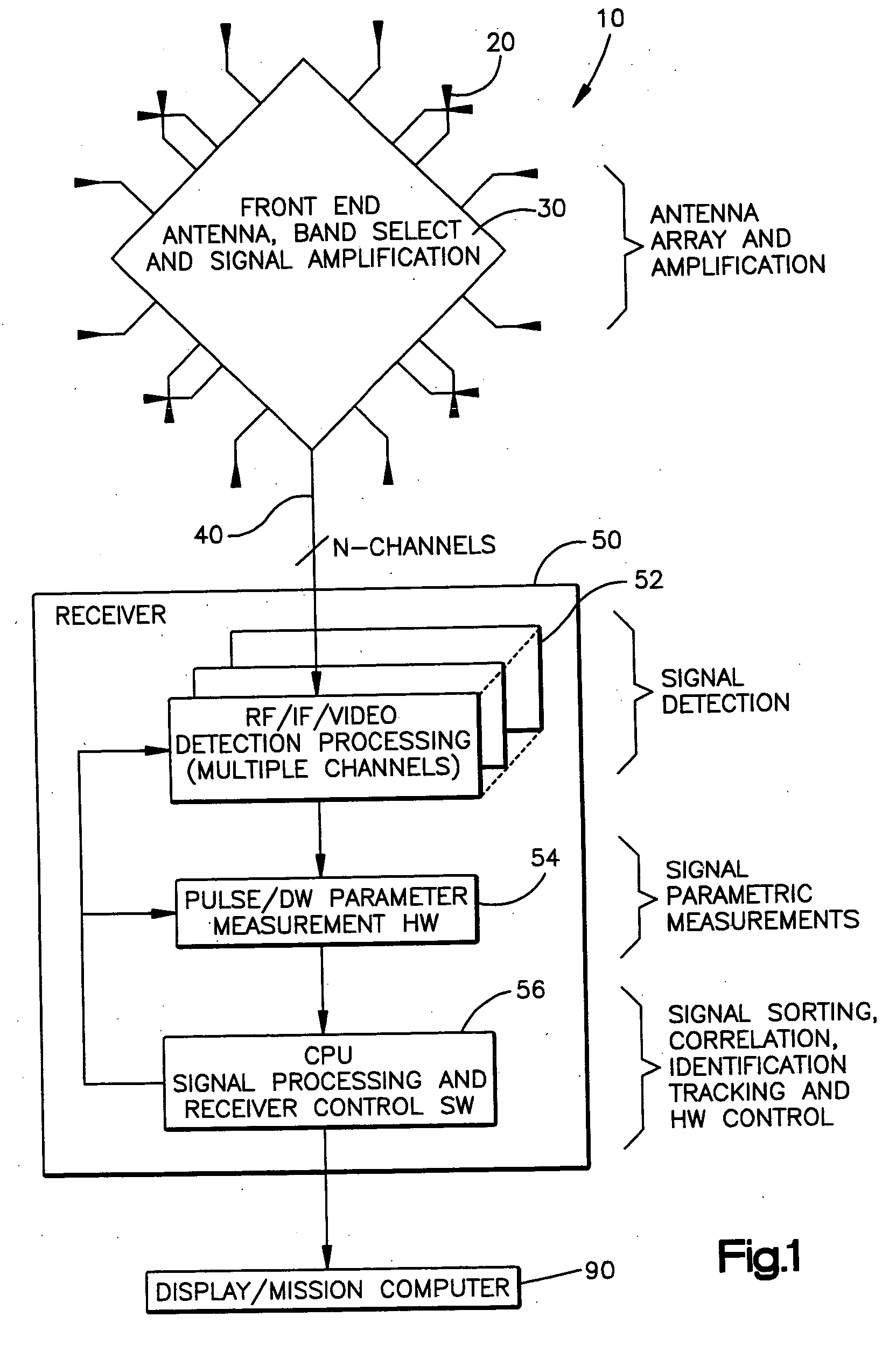
[0016] Electronic support measure (ESM) receiver systems typically are ground based, airborne, or sea based (surface or sub-surface platforms) systems that passively detect threat signals of interest, typically radar and communication signals. An ESM system identifies, classifies, and prioritizes detected signals for display to an operator or crew. The goal is to provide the crew with a tactical picture, or “situational awareness”, of the electromagnetic environment around them, such that the crew may react and counter any threats (e.g., maneuver, apply counter measure, attack, etc.). Since signal detection is passive (only receiving), an ESM receiver cannot be detected (i.e., an operator of a threat does not know that the ESM is in operation or that the threat has been detected, identified, and possibly located, etc.).

[0017] Although there are many variations, a typical ESM receiver system 10, as seen in FIG. 1, consists of an antenna array 20, low noise preamplifier 30, antenna c...


PUM


Abstract

A system time thresholds dwells executed by an electromagnetic signal receiver. The system includes a detection module and a processing module. The detection module receives electromagnetic signals from a surrounding environment. The electromagnetic signals are chronologically segregated into a plurality of dwells each with a dwell time. The processing module controls the scanning of the surrounding environment. The processing module sets dwell parameters and determines whether to skip the execution of particular dwells. The processing module receives data about the signals from the detection module.

Description

FEDERAL SPONSORSHIP [0001] The U.S. Government has a paid-up license in this invention and the right, in limited circumstances, to require the patent owner to license others on reasonable terms as provided for by the terms of Contract No. N00019-97-C-0147 awarded by the U.S. Navy.FIELD OF INVENTION [0002] The present invention relates to a system for signal processing and, more specifically, a system for time thresholding. BACKGROUND OF THE INVENTION [0003] Typically, transmitted signals are collected by a receiver and processed during predetermined time intervals called dwells. The processing of signals received during a previous dwell occurs during a subsequent dwell. An inter-dwell period exists between dwells to allow for the reconfiguration of data processing circuits and other hardware in response to the processed data of the most recent dwell. Any processing of received signals or collecting of received signals is typically halted during this inter-dwell period. [0004] A syst...

Claims


Application Information

Patent Timeline
Patent Type & Authority Applications(United States)
IPC IPC(8): G01S7/02
CPCG01S7/021
Inventor BRICKER, JEFFREY K.GOUNALIS, ANTHONY J.
Owner LOCKHEED MARTIN CORP
Why Eureka
Try Eureka