Enhancement on radio link failure report to record necessary timing details for a dual-threshold handover trigger event

a radio link and trigger event technology, applied in the field of radio link failure (rlf) condition, can solve the problems of radio link failure (rlf) being considered to have occurred, rlf due to ho process being considered a mobility failure, etc., to prevent unnecessary waste of processing resources, improve the resolution of rlf issue, and improve the picture

Active Publication Date: 2015-04-02
TELEFON AB LM ERICSSON (PUBL)
View PDF4 Cites 55 Cited by
  • Summary
  • Abstract
  • Description
  • Claims
  • Application Information

AI Technical Summary

Benefits of technology

[0046]The system time-based timestamp information in an RLF report according to particular embodiments of the present disclosure provides the source cell with a better picture of why RLF happens and, hence, enables the source cell to provide a better resolution of the RLF issue instead of unnecessarily, and probably incorrectly, adjusting the event-specific threshold level(s) for an HO-triggering event. The present disclosure not only helps preventing the unnecessary wastage of processing resources at a UE, but also allows an exact recollection of when mobility failure-related actions occurred at the UE. The additional timing information according to particular embodiments of the present disclosure enables the source cell to not limit its resolution of the RLF issue to adjustment of threshold level(s), but to also explore the adjustment of a TTT interval or other cell coverage related parameters depending on the true root cause of the RLF associated with the HO.

Problems solved by technology

However, if the UE fails to complete the HO during the HO interruption period 30, Radio Link Failure (RLF) is considered to have occurred.
RLF due to HO process is considered a mobility failure.

Method used


Image

  • Enhancement on radio link failure report to record necessary timing details for a dual-threshold handover trigger event
  • Enhancement on radio link failure report to record necessary timing details for a dual-threshold handover trigger event
  • Enhancement on radio link failure report to record necessary timing details for a dual-threshold handover trigger event

Examples


Embodiment Construction

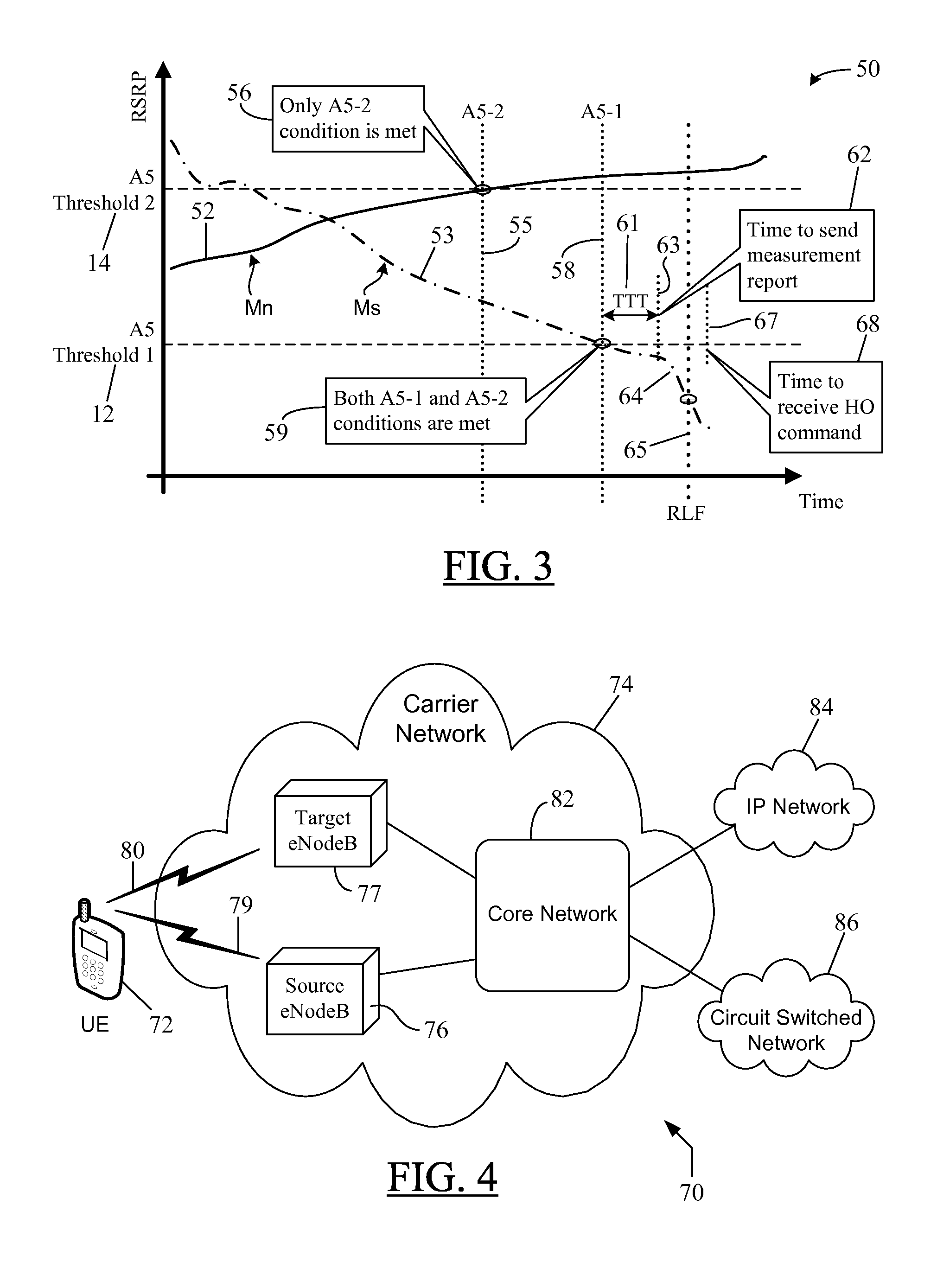
[0056]In the following detailed description, numerous specific details are set forth in order to provide a thorough understanding of the disclosure. However, it will be understood by those skilled in the art that the present disclosure may be practiced without these specific details. In other instances, well-known methods, procedures, components and circuits have not been described in detail so as not to obscure the present disclosure. It should be understood that the disclosure is described primarily in the context of a Third Generation Partnership Project (3GPP) cellular telephone / data network such as, for example, an LTE network, but it can be implemented in other forms of cellular or non-cellular wireless networks as well. Thus, the use of the term “cell”—as in the “serving cell,”“source cell,”“neighbor cell,” or the “target cell”—in the discussion below should not be construed to be limited to a cellular structure only.

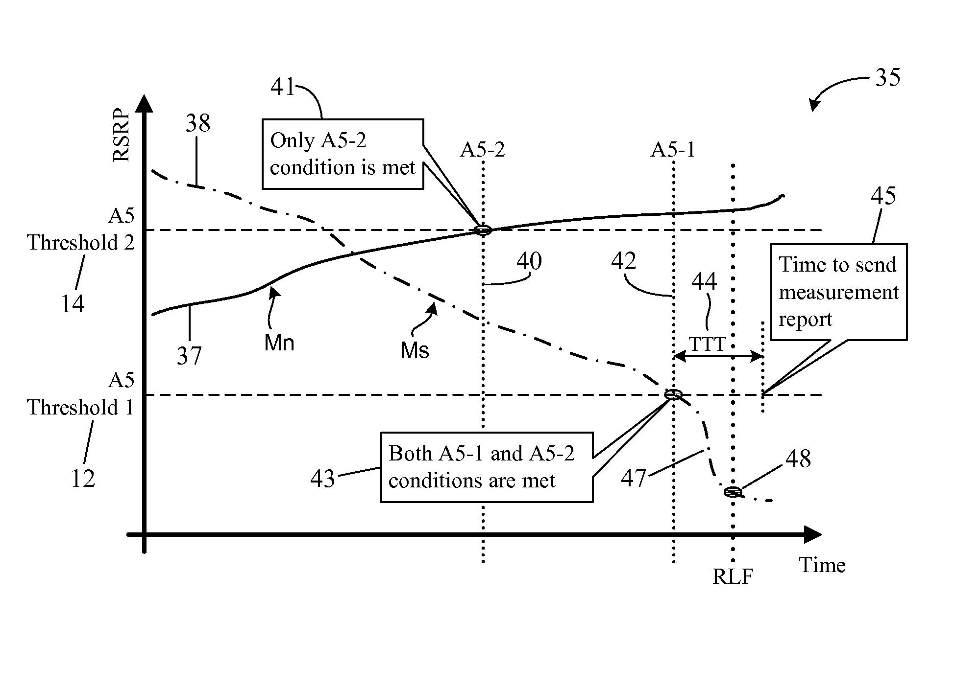
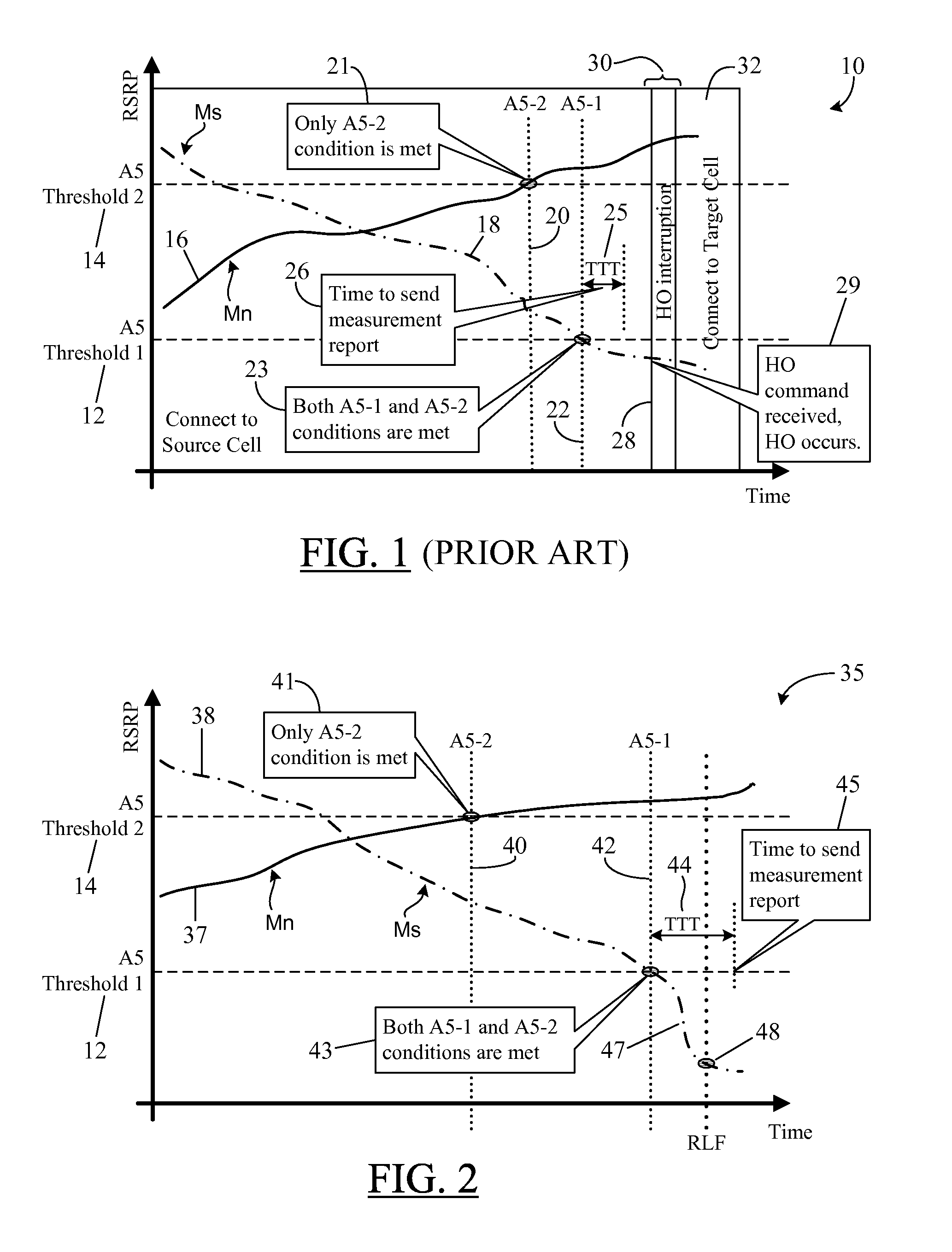
[0057]FIG. 2 is an exemplary plot 35 depicting a “too late ...


PUM


Abstract

A system and method in which a Radio Link Failure, RLF, report from a User Equipment, UE, provides system time-based timestamps to enable a source node to correctly analyze the real cause of an RLF associated with a handover. The timestamps are provided for the latest fulfillment of each event-specific entering condition associated with a handover-triggering event and for the occurrence of the RLF. The recorded timestamps are sent as part of RLF-reporting information to be forwarded to the source node to assist the source node in adjusting event-specific threshold(s) as well as other non-threshold related handover parameters such as the Time To Trigger, TTT, period, the time delay between a UE's transmission of its Measurement Report and the source node's transmission of the handover command, and the like, to reduce similar RLFs in the future. The generation of timestamps does not waste the UE's processing resources or battery power.

Description

CROSS-REFERENCE TO RELATED APPLICATIONS[0001]This application claims the priority benefit under 35 U.S.C. §119(e) of U.S. Provisional Application No. 61 / 884,552 filed on Sep. 30, 2013, the disclosure of which is incorporated herein by reference in its entirety.TECHNICAL FIELD[0002]The present disclosure relates to a Radio Link Failure (RLF) condition in a mobile communication network. More particularly, and not by way of limitation, particular embodiments of the present disclosure are directed to a system and method of enhancing an RLF report related to an RLF associated with a handover (HO), wherein the enhanced RLF report includes additional timing details of an HO-triggering event based on the common system time to enable a source cell to better identify the root cause of the RLF and to thereby provide a better resolution to address the RLF.BACKGROUND[0003]In cellular communication, the most basic form of “handover” or “handoff” is when a phone call or other communication session...

Claims


Application Information

Patent Timeline
Patent Type & Authority Applications(United States)
IPC IPC(8): H04W24/08H04W36/00
CPCH04W36/00H04W24/08H04W36/0094H04W36/0058H04W36/0079
Inventor JANG, KE-CHICENTONZA, ANGELO
Owner TELEFON AB LM ERICSSON (PUBL)
Why Eureka
Try Eureka