Image-sensing apparatus

Inactive Publication Date: 2005-03-10
SONY SEMICON SOLUTIONS CORP
View PDF10 Cites 65 Cited by
  • Summary
  • Abstract
  • Description
  • Claims
  • Application Information

AI Technical Summary

Benefits of technology

According to the present invention, by the use of a look-up table, it is possible to perform white balance processing, accurately and with a simple configuratio

Problems solved by technology

However, in the image-sensing apparatuses proposed in Japanese Patent Applications Laid-Open Nos. 2002-10275 and 2002-290980, while white balance processing is effective for an image signal outputted from a solid-state image sensor that performs photoelectric conversion only with logarithmic conversion characteristics, it does not work with a solid-state image sensor that performs photoelectric c

Method used


Image

  • Image-sensing apparatus
  • Image-sensing apparatus
  • Image-sensing apparatus

Examples


Embodiment Construction

Configuration of Image-Sensing Apparatus

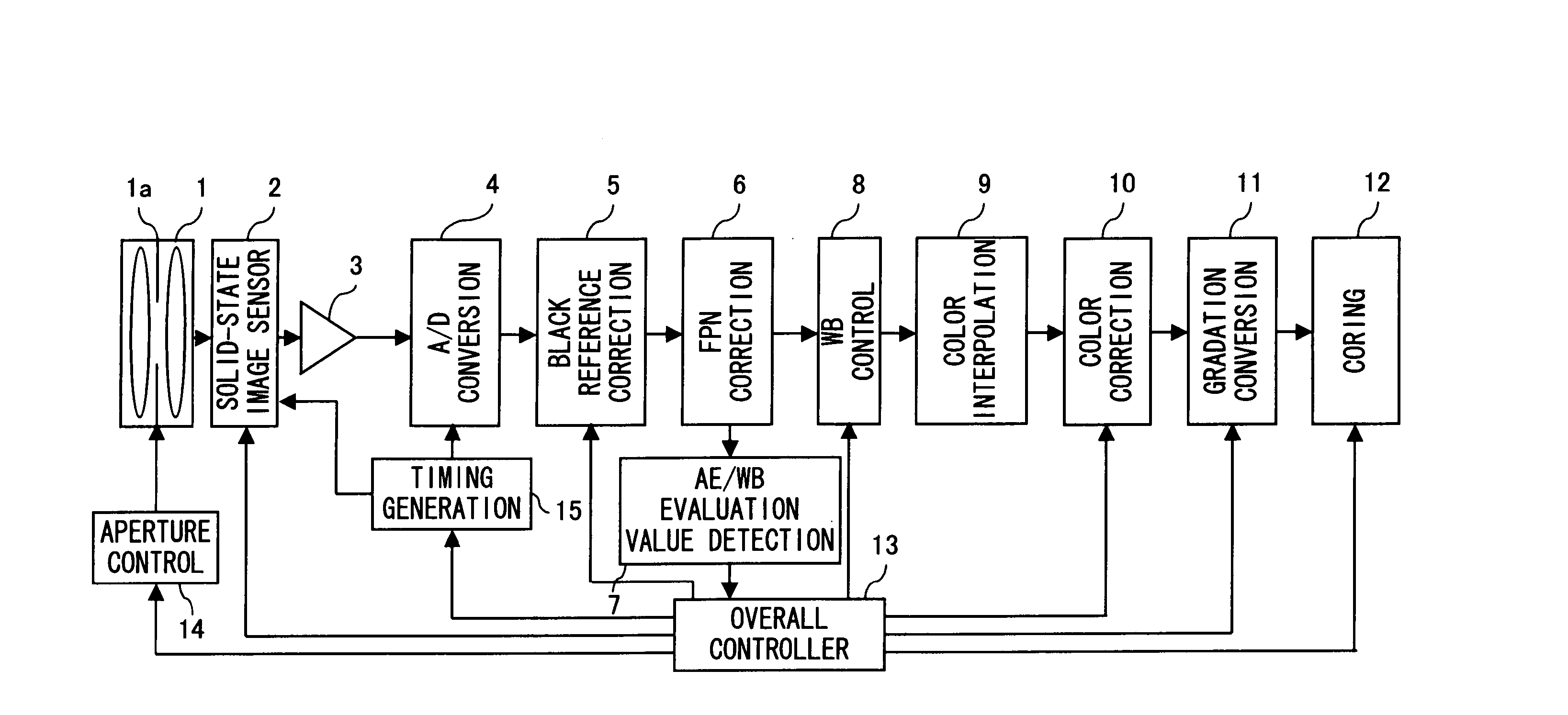
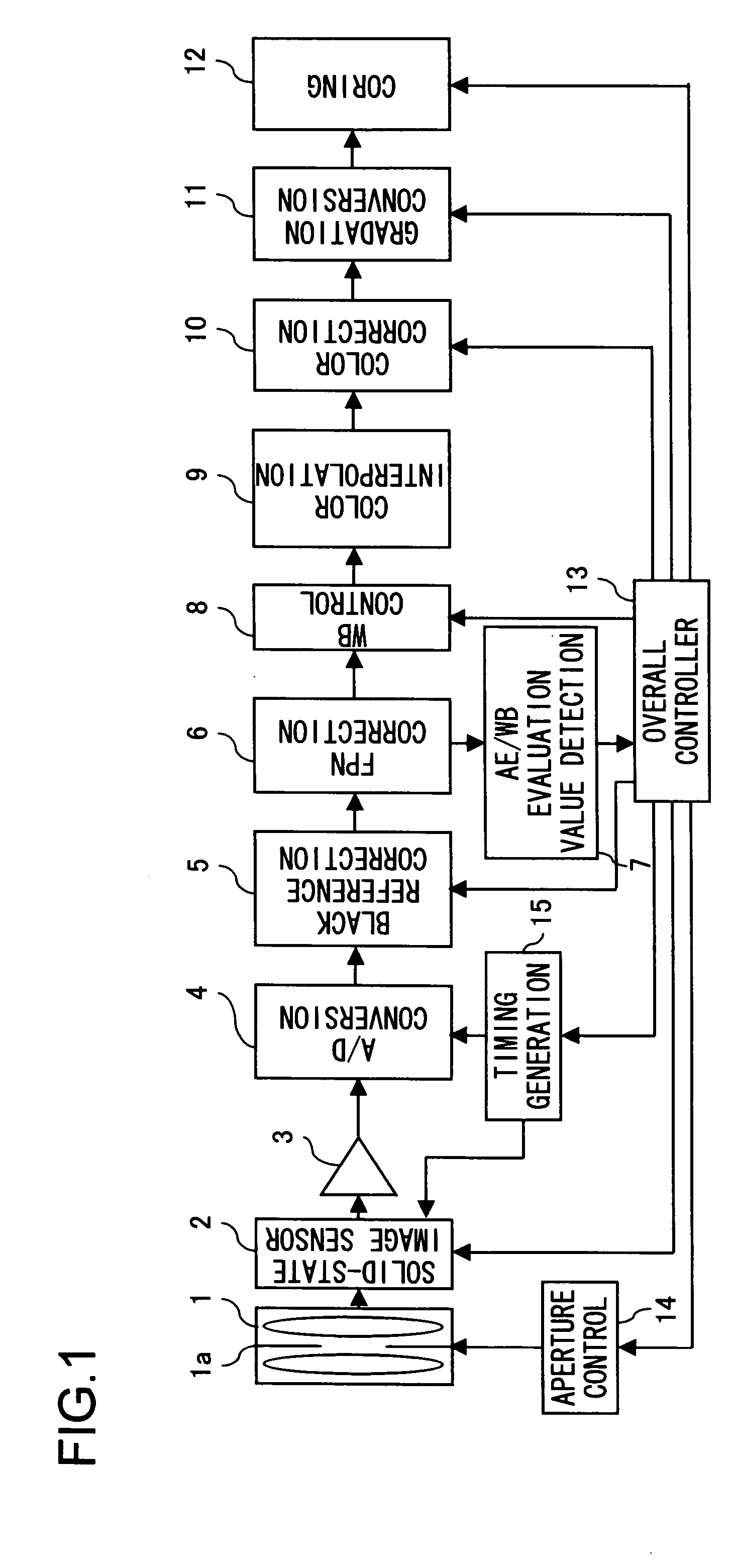
The configuration of an image-sensing apparatus embodying the present invention will be described with reference to FIG. 1. FIG. 1 is a block diagram showing the internal configuration of an image-sensing apparatus.

The image-sensing apparatus shown in FIG. 1 includes an optical system 1 composed of a plurality of lens elements; a solid-state image sensor 2 that converts the amount of light incident through the optical system 1 into an electrical signal; an amplifier 3 that amplifies the electrical signal outputted from the solid-state image sensor; an AD conversion circuit 4 that converts the electrical signal amplified by the amplifier 3 into a digital signal; a black reference correction circuit 5 that sets the minimum level of the digital signal outputted from the AD conversion circuit 4; an FPN (fixed pattern noise) correction circuit 6 that eliminates FPN noise resulting from the differences in sensitivity among the individual pixels...


PUM


Abstract

A database obtained based on the photoelectric conversion characteristics for R and G signals and a database obtained based on the photoelectric conversion characteristics for G and B signals are stored in LUTs respectively. Signal value calculators read out the databases from the LUTs respectively and perform white balance processing on the R and B signals respectively.

Description

This application is based on Japanese Patent Application No. 2003-316534 filed on Sep. 9, 2003, the contents of which are hereby incorporated by reference. BACKGROUND OF THE INVENTION 1. Field of the Invention The present invention relates to an image-sensing apparatus for sensing a color image which is provided with a solid-state image sensor having a plurality of types of color filters so as to output chrominance signals. More particularly, the present invention relates to an image-sensing apparatus that performs white balance processing on chrominance signals. 2. Description of the Prior Art Conventionally, a solid-state image sensor that performs linear conversion by converting the amount of incident light linearly for output has a narrow dynamic range, typically a two-digit figure. Thus, when it is used to shoot a subject with a brightness distribution spread over a wide range of brightness, it does not output brightness information outside its dynamic range. As a differen...

Claims


Application Information

Patent Timeline
IPC IPC(8): H04N1/46H04N9/73
CPCH04N9/735H04N23/88
Inventor MINAKUTI, JUNKAMON, KOICHIKUSUDA, MASAYUKI
Owner SONY SEMICON SOLUTIONS CORP
Why Eureka
Try Eureka