Ethernet converter

a technology of ethernet converter and converter, which is applied in the direction of network connector, transmission, coupling device connection, etc., can solve the problems of substantial time and resource costs of rewiring a building with the necessary cables

Inactive Publication Date: 2005-03-10
PULYK GARRY ALLEN
View PDF5 Cites 107 Cited by
  • Summary
  • Abstract
  • Description
  • Claims
  • Application Information

AI Technical Summary

Problems solved by technology

However the costs in time and resources associated with rewiring a building with the necessary cables can be substantial.

Method used


Image

  • Ethernet converter
  • Ethernet converter
  • Ethernet converter

Examples


Embodiment Construction

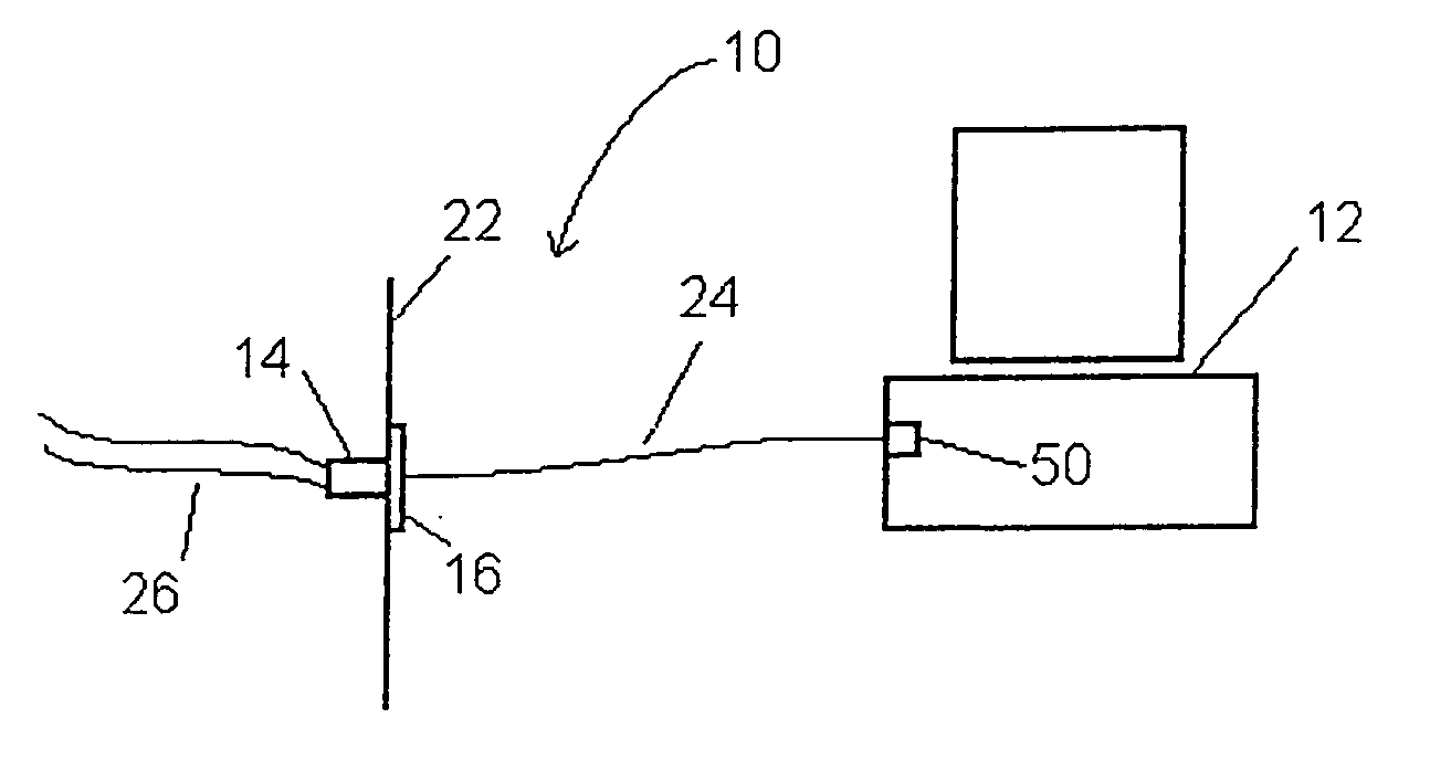
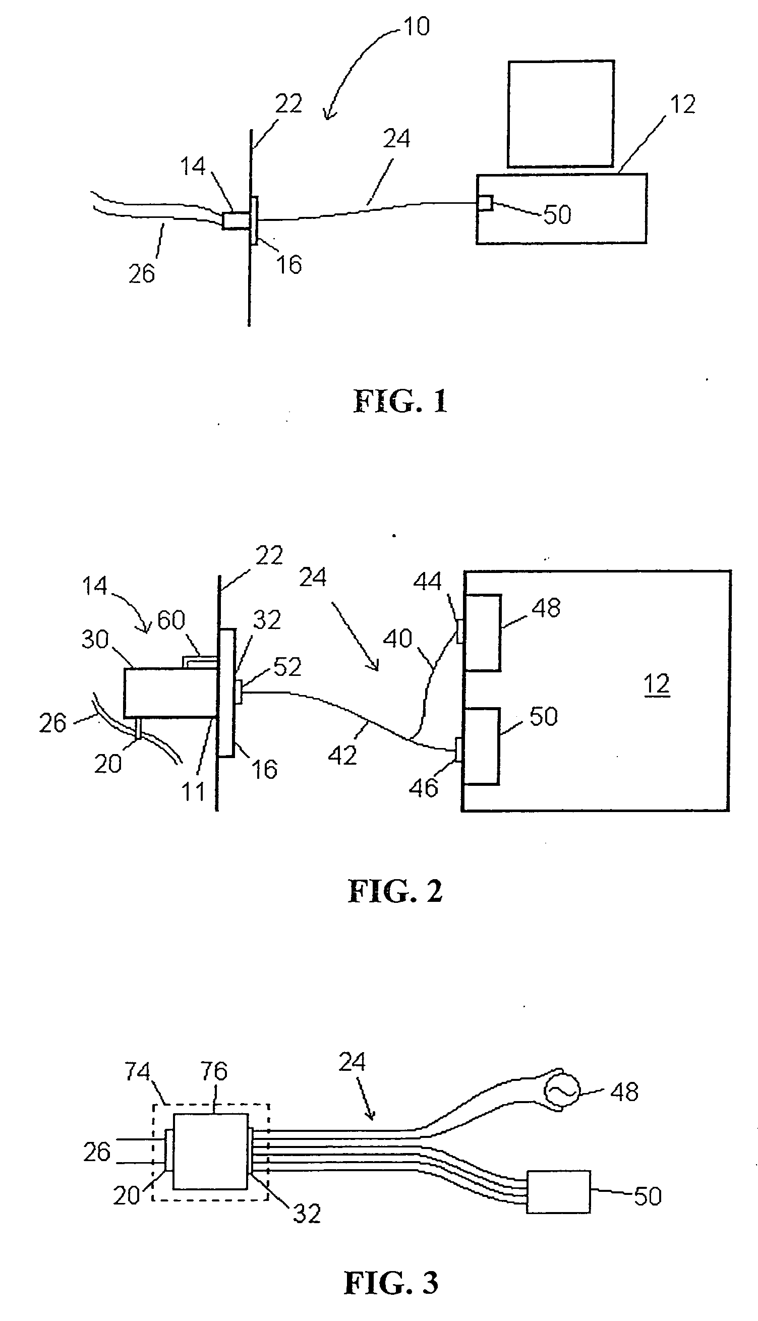
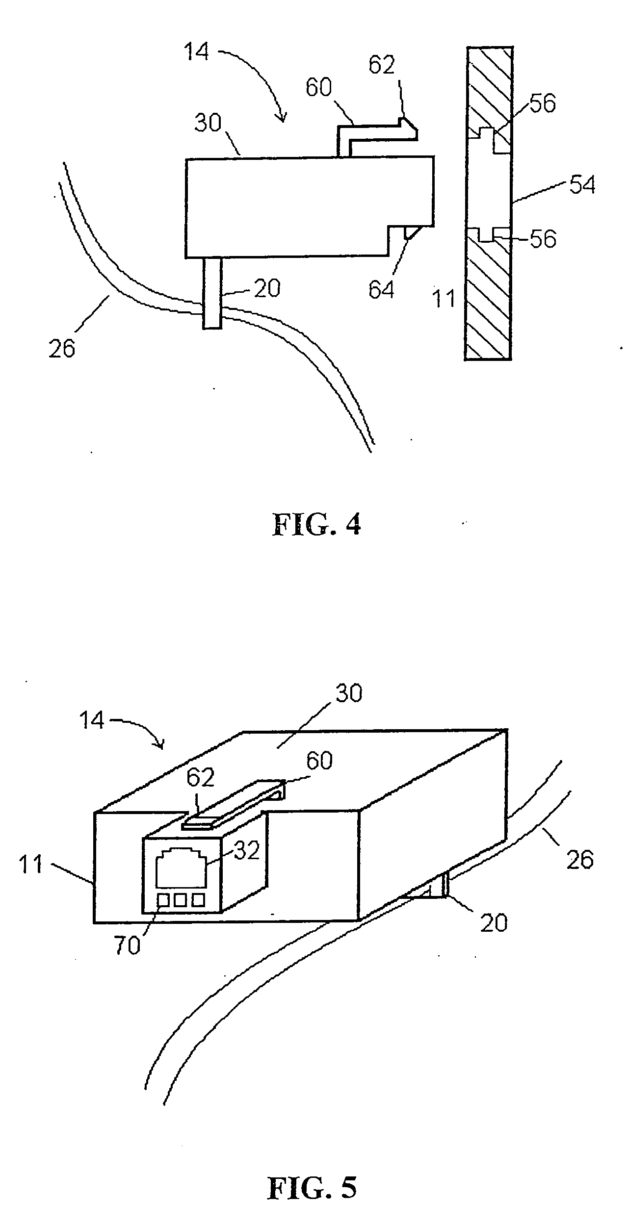
[0013]FIG. 1 shows a system 10 that enables a computer 12 with an ethernet port 50 to transmit data on a two-wire system 26. The system 10 comprises a data port 14 for converting data transmitted on an ethernet to data transmitted on a two-wire system 26 A connector or computer cable 24 is shown connecting the device 14 to the computer 12. In FIG. 1, the power source of the data port is not shown, although according to a preferred embodiment, a power source is required. The power source can be any source that allows the device to function. Some examples of possibilities a USB port or a PS / 2 port on a computer, or an AC / DC adapter to be plugged into an electrical outlet. Other power sources that are common could also be used, such as a removable battery. More detail is shown in FIG. 2, where the data port 14 is shown to comprise a wall mountable housing 30, and a RJ11 port 32 at a first end 11, or the front end, which will be inserted into an opening in the wall plate 16. This allows...


PUM


Abstract

An ethernet converter enables computers with an ethernet connection to connect to a network on a two-wire system. The converter comprises a device installed behind a wall plate that employs an RJ11 port. The converter may comprise indicator lights, which notifies the user of the status of the converter. The converter may comprise a cable for connecting the computer to the device, and for connecting the device to a power source, which may be a USB port or a PS / 2 port of the computer, or an AC / DC adapter connected to an AC power source.

Description

BACKGROUND OF THE INVENTION [0001] There is an increasing demand for network accessibility in many areas, such as the hospitality industry. However the costs in time and resources associated with rewiring a building with the necessary cables can be substantial. It is, therefore, convenient to provide converters that allow a user to access the network on the existing wiring. Products available from the inventor under the market name of Extreme I and Extreme II can be installed behind an existing face plate and attach directly to the existing wires, and allows a user to access the network through a USB port in the face plate. This requires the installation of the necessary device driver onto the computer, which can be done by either supplying the user with the necessary software, or the USB connection can self-install the necessary software (plug and play). This invention has as an object to provide a converter that operates on the existing wiring with a simple installation but does n...

Claims


Application Information

Patent Timeline
Patent Type & Authority Applications(United States)
IPC IPC(8): H01R31/06
CPCH01R2201/04H01R31/065
Inventor PULYK, GARRY ALLEN
Owner PULYK GARRY ALLEN
Why Eureka
Try Eureka