Focused photon energy heating chamber

a technology of focused photon and heating chamber, which is applied in the direction of lighting and heating apparatus, muffle furnaces, furnaces, etc., can solve the problems of crystal defects and slip dislocations in wafers, limited power density of direct radiation, and conventional lamp-based rtp systems with considerable drawbacks. , to achieve the effect of improving the thermal uniformity and ramp rate of the design

Inactive Publication Date: 2005-03-10
WAFERMASTERS
View PDF4 Cites 7 Cited by
  • Summary
  • Abstract
  • Description
  • Claims
  • Application Information

AI Technical Summary

Benefits of technology

[0009] The present invention includes an apparatus and method for heating substrates, such as semiconductor wafers. In the present invention, a radiation energy source is arranged proximate to a reflector to direct radiation towards a window providing optical access to a processing chamber. A lens positioned outside of the window can efficiently focus the radiation emitted from the radiation energy source and reflector and direct it through the window. The focused radiation energy can be used to directly or indirectly heat a semiconductor wafer disposed in the processing chamber. The use of the lens to focus the intensity of the radiation significantly improves the thermal uniformity and ramp rate of the design.
[0010] The radiation from the radiation energy source can be focused and directed by the lens through the window towards a heat absorbing member on which the wafer is placed. By heating the heat absorbing member, the wafer can be subjected to more uniform heating and thus, the apparatus can provide reproducible results. The intense heating of the heat absorbing member also allows for a high heating ramp rate.

Problems solved by technology

Conventional lamp-based RTP systems have considerable drawbacks with regard to achieving and maintaining a uniform temperature distribution across the active layer of the wafer surface.
However, the power density of direct radiation is limited by the rating of lamps and further by packing density of the lamps.
Temperature fluctuations occur on the surface of the wafer which may cause crystal defects and slip dislocations in the wafer at high temperatures (e.g. ˜1000° C.).
Further, the heating ramp rate and maximum temperature achievable are limited by the power density of the lamps.

Method used


Image

  • Focused photon energy heating chamber
  • Focused photon energy heating chamber
  • Focused photon energy heating chamber

Examples


Embodiment Construction

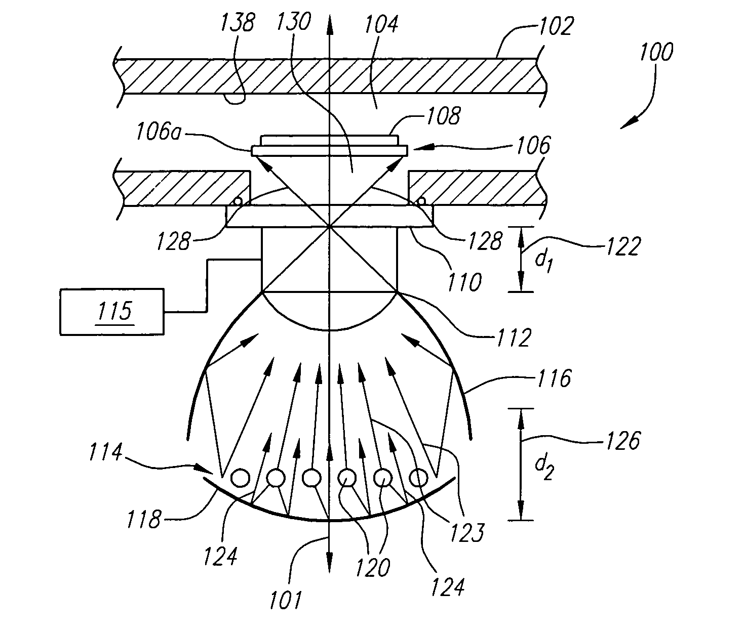
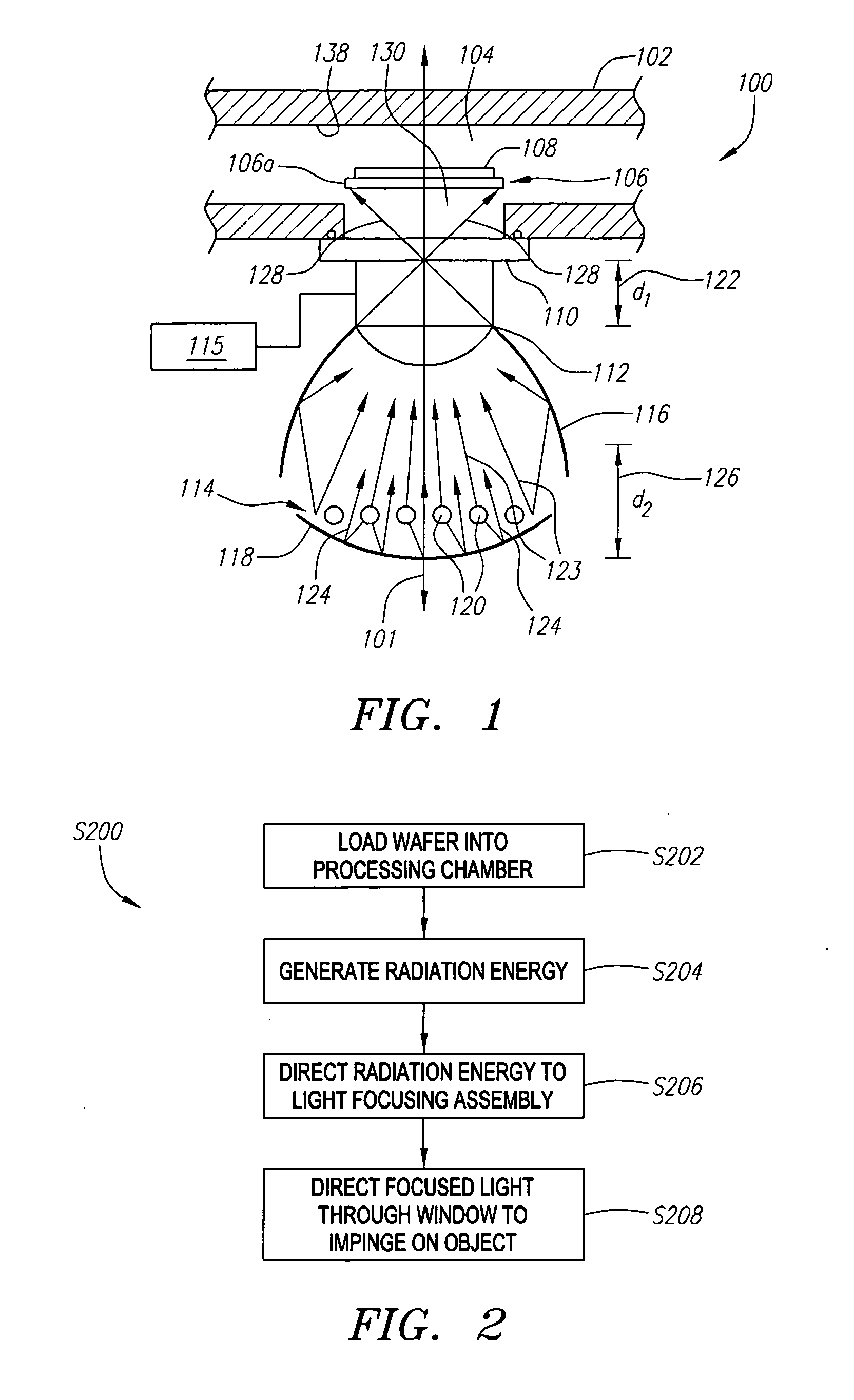
[0020]FIG. 1 is a simplified representation of the wafer heating apparatus of the present invention. Heating apparatus 100 includes a processing chamber 102 defining a processing area 104. Optionally, disposed within processing area 104 is a heat absorbing member 106 used to support a single wafer 108 during processing. A window 110 is formed or mounted onto processing chamber 102 to provide optical access along an optical path 101 to processing area 104. External to processing chamber 102 and positioned substantially along optical path 101 are a radiation focusing assembly 112, a radiation source 114, and a strategically positioned radiation reflecting device 118.

[0021] It should be understood that optical path 101 is represented by a line segment merely to provide an illustrative representation of the line-of-sight access through window 110 into process chamber 102 upon which some of the components of heating apparatus 100 are generally aligned. Optical path 101 is shown perpendi...


PUM

PropertyMeasurementUnit
temperaturesaaaaaaaaaa
thickaaaaaaaaaa
heightaaaaaaaaaa

Abstract

An apparatus and method for heating substrates, such as semiconductor wafers. A radiation energy source is arranged proximate to a reflector to direct radiation towards a window providing optical access to a processing chamber. A lens positioned outside of the window focuses the radiation emitted from the radiation energy source and reflector and directs it through the window. The focused radiation energy can be used to directly or indirectly heat a semiconductor wafer disposed in the processing chamber.

Description

BACKGROUND [0001] 1. Field of the Invention [0002] This invention generally relates to semiconductor manufacturing equipment and, more particularly, to an apparatus and method used for the processing of semiconductor wafers. [0003] 2. Description of the Related Art [0004] In the semiconductor industry, advancements in the development of semiconductor devices of decreased dimensions require the development of new processing and manufacturing techniques. One such processing technique is known as Rapid Thermal Processing (RTP). The RTP technique reduces the amount of time that a semiconductor device is exposed to high temperatures during processing. The RTP technique, typically includes irradiating the semiconductor device or wafer with sufficient power to rapidly raise the temperature of the wafer and maintaining the temperature for a time period long enough to successfully perform a fabrication process, but which avoids such problems as unwanted dopant diffusion that would otherwise ...

Claims


Application Information

Patent Timeline
Patent Type & Authority Applications(United States)
IPC IPC(8): H01L21/00
CPCH01L21/67115
Inventor YOO, WOO SIK
Owner WAFERMASTERS
Why Eureka
Try Eureka