
System and method for marking the surface of a semiconductor package

a technology of semiconductor packages and surface markings, applied in the field of semiconductor packages, can solve the problems of reducing the distance between the surface of the semiconductor package and the highest wire loop position, increasing danger, and increasing danger

Inactive Publication Date: 2005-03-10
TEXAS INSTR INC
View PDF8 Cites 4 Cited by
  • Summary
  • Abstract
  • Description
  • Claims
  • Application Information

AI Technical Summary

Benefits of technology

[0003] According to the present invention, certain disadvantages and problems associated with previous techniques for marking a surface of a semiconductor package may be reduced or eliminated.
[0006] Particular embodiments of the present invention may provide one or more technical advantages. In certain embodiments, marking the surface of the semiconductor package according to a printing pattern that excludes an excluded surface portion of the surface of the semiconductor package may reduce or eliminate damage to wire loops or other components of the semiconductor package caused by marking the surface. In certain embodiments, marking the surface of the semiconductor package according to the present invention may allow semiconductor package thickness to be reduced without substantially reducing the reliability or strength of the semiconductor package. In certain embodiments, the present invention may reduce or eliminate reductions in the strength of the mold compound package body or other package body of the semiconductor package resulting from marking the surface of the semiconductor package.

Problems solved by technology

A danger may exist that marking the surface of the package body may damage one or more wire loops or other components of the semiconductor package, at the highest wire loop position for example.
As the size of semiconductor packages decreases, this danger may increase because the distance between the surface of the semiconductor package and the highest wire loop position may decrease.
The laser marking may also damage the structural integrity of the package body if the marking of the surface reduces the distance between the surface of the package body and the highest wire loop position by an undesirable amount.

Method used


Image

  • System and method for marking the surface of a semiconductor package
  • System and method for marking the surface of a semiconductor package
  • System and method for marking the surface of a semiconductor package

Examples


Embodiment Construction

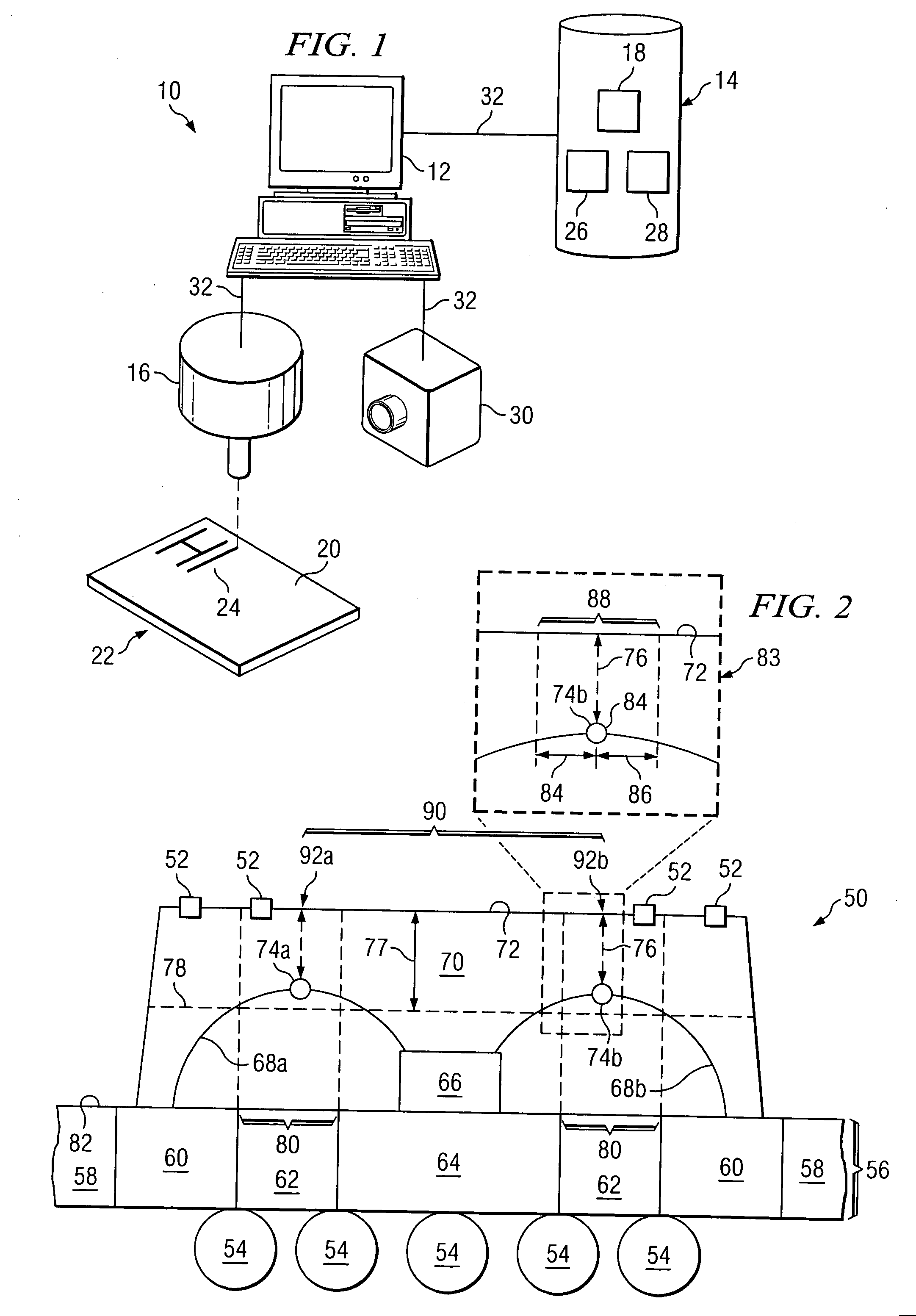
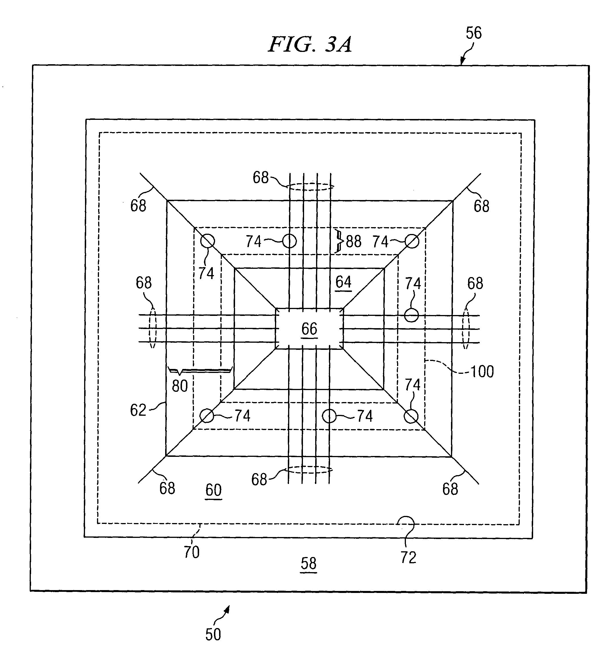
[0014]FIG. 1 illustrates an example system 10 for marking a surface of a semiconductor package. System 10 may include a computer system 12, a memory 14, and marking equipment 16. In general, computer system 12 is operable to determine a printing pattern 18 for marking a surface 20 of a semiconductor package 22, and marking equipment 16 is operable to mark surface 20 of semiconductor package 22 with one or more marks 24 according to the determined printing pattern 18. Printing pattern 18 may exclude an excluded surface portion of surface 20 of semiconductor package 22, the excluded surface portion corresponding to one or more highest element positions within semiconductor package 22. This description focuses on an embodiment in which the element comprises a wire loop of the semiconductor package and the highest element position comprises a highest wire loop position. However, the present invention contemplates the element being any suitable component of a semiconductor package and th...


PUM


Abstract

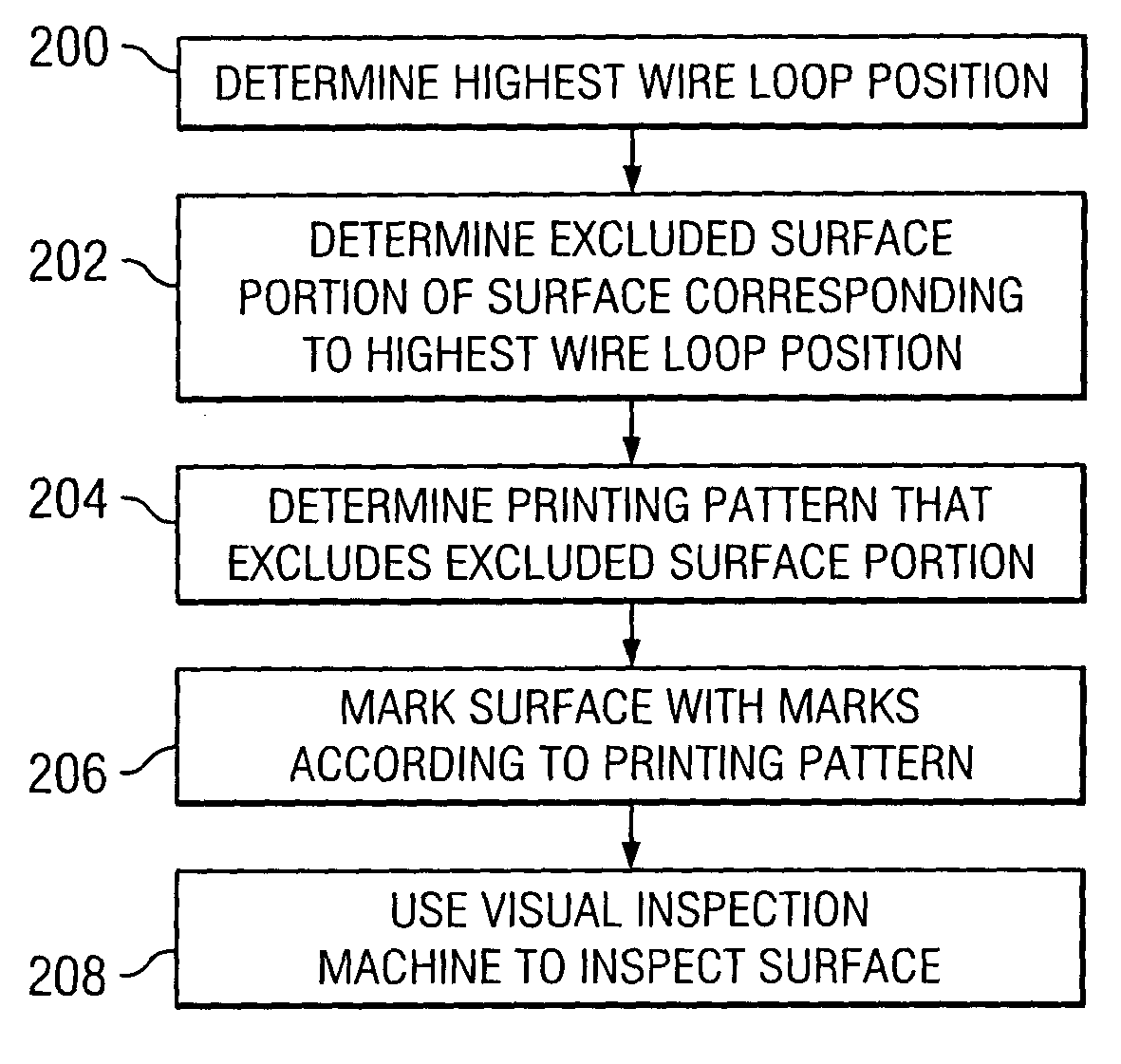
In one embodiment, a method for marking a surface of a semiconductor package comprises determining a highest element position within the semiconductor package and determining an excluded surface portion of a surface of the semiconductor package corresponding to the highest element position. The method further comprises determining a printing pattern for marking the surface of the semiconductor package with one or more marks, the printing pattern excluding the excluded surface portion of the surface of the semiconductor package. The method further comprises marking the surface of the semiconductor package with the one or more marks according to the determined printing pattern.

Description

TECHNICAL FIELD OF THE INVENTION [0001] This invention relates generally to semiconductor packages and more particularly to a system and method for marking the surface of a semiconductor package. BACKGROUND [0002] Semiconductor packages such as integrated circuit packages generally include one or more wire bonds connecting a first component of the semiconductor package to one or more second components of the semiconductor package. A package body generally surrounds the wire bonds and the first and second components such that a distance exists between a surface of the package body and a highest wire loop position or other component of the semiconductor package. It is often desirable to mark a surface of the semiconductor package, on a surface of the package body for example. A danger may exist that marking the surface of the package body may damage one or more wire loops or other components of the semiconductor package, at the highest wire loop position for example. As the size of se...

Claims


Application Information

Patent Timeline
IPC IPC(8): H01L21/66H01L23/544
CPCH01L23/544H01L2224/48091H01L2223/54406H01L2223/54486H01L2224/45144H01L2224/49171H01L2224/49175H01L2924/01079H01L2924/14H01L2924/15311H01L24/45H01L2224/48227H01L24/48H01L24/49H01L2924/00014H01L2924/00H01L2924/12042H01L2924/181H01L2924/00012
Inventor MATSUNAMI, AKIRA
Owner TEXAS INSTR INC
Learn More