Electrode connector for ring laser gyros

a technology of electro-optical connectors and laser gyros, which is applied in the direction of coupling device connections, functional valve types, transportation and packaging, etc., can solve the problems of brittle ceramic plate damage, assembly failures that tend to be premature, etc., and achieve the effect of reducing oxidation, electrical contact resistance and embrittlemen

Inactive Publication Date: 2008-09-30
HONEYWELL INT INC
View PDF2 Cites 2 Cited by
  • Summary
  • Abstract
  • Description
  • Claims
  • Application Information

AI Technical Summary

Benefits of technology

[0010]In yet other aspects of the invention, the wire material is selected to incorporate nickel plated stainless steel to reduce oxidation, electrical contact resistance and embrittlement in a high temperature or other oxidizing environment.

Problems solved by technology

Because of both the high temperatures employed and the manipulation required mounting and demounting leadwires of the connector, assemblies have a tendency to fail prematurely.
In addition, the brittle ceramic plate is subject to damage over the course of normal use.

Method used


Image

  • Electrode connector for ring laser gyros
  • Electrode connector for ring laser gyros
  • Electrode connector for ring laser gyros

Examples


Embodiment Construction

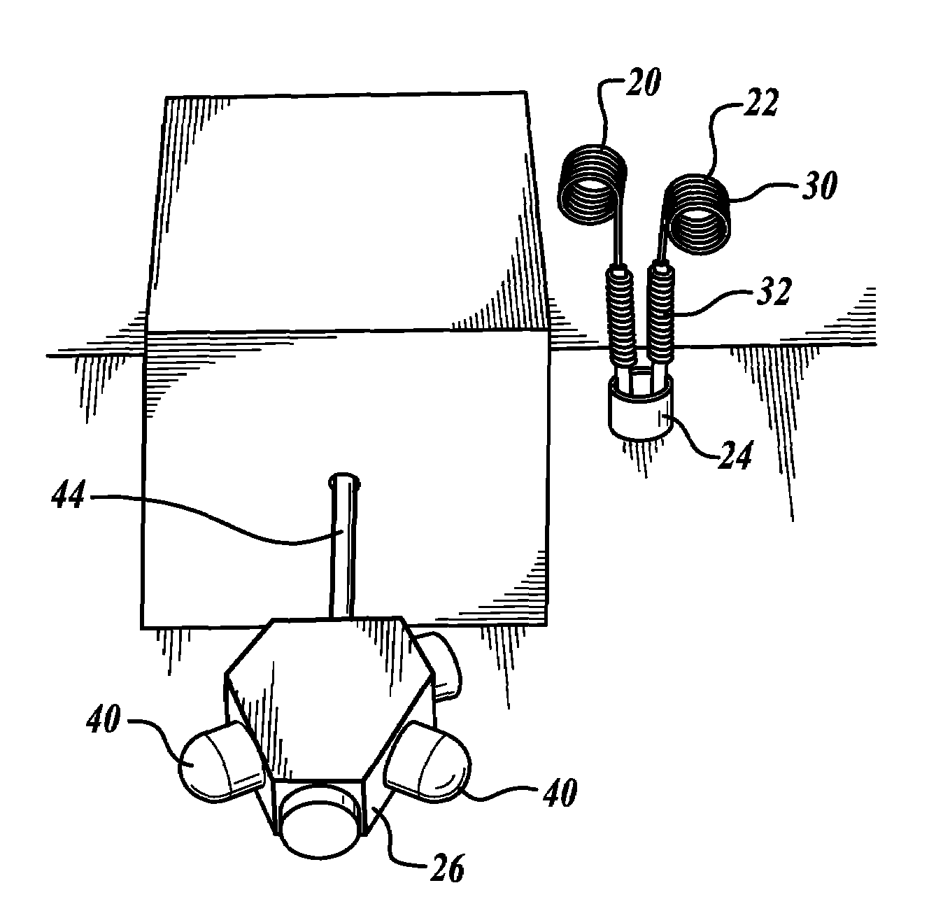
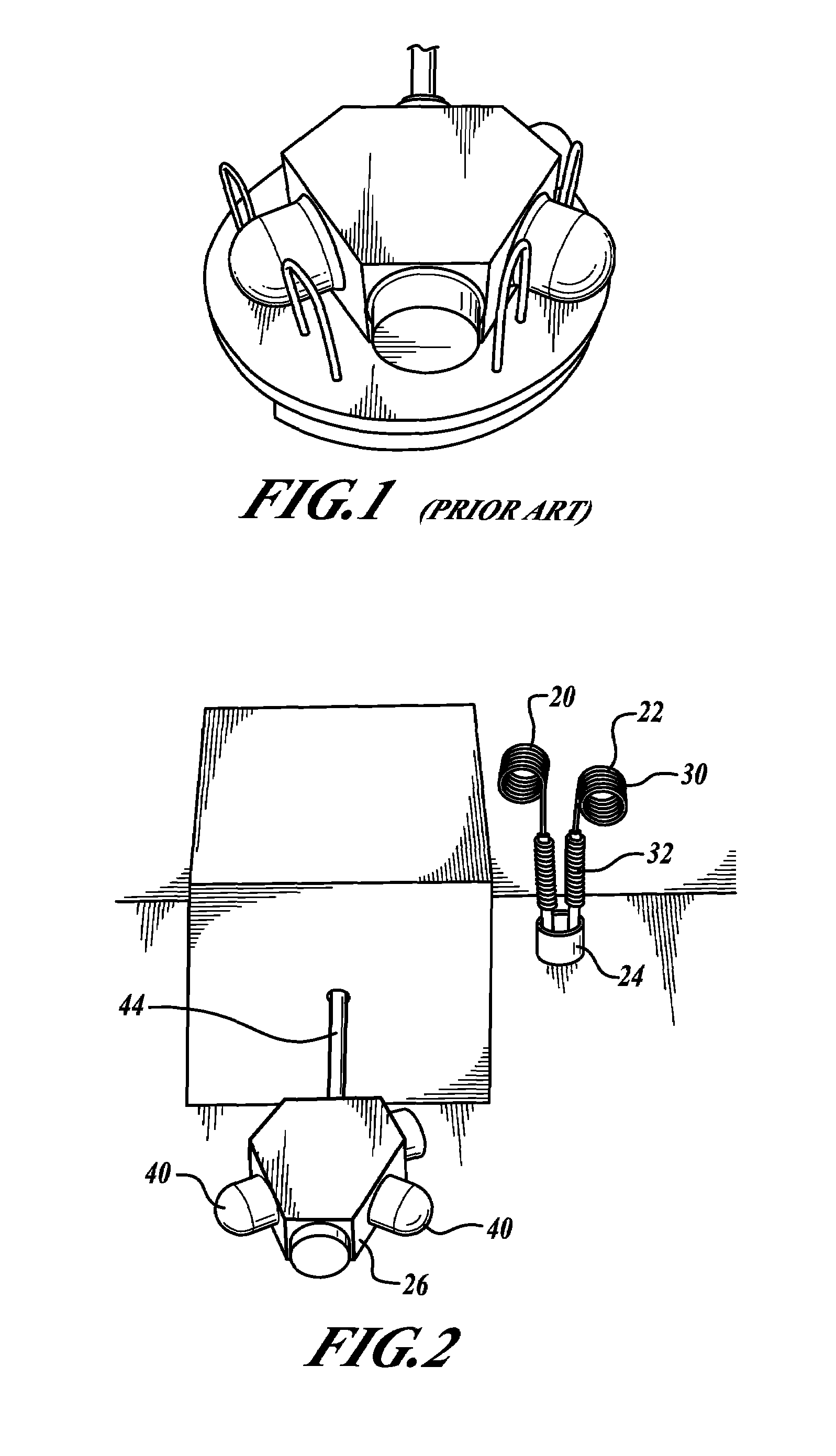
[0015]FIGS. 2-4 illustrate perspective views of a portion of a gas fill process device 28 having a laser block assembly (LBA) 26 mounted thereto. The device 28 includes torsional electrode connectors 20, 22 that are received in a storage seat 24 and are electrically connected to a voltage source (not shown) of the device 28. The device 28 includes one or more gas supply structures 44 that an LBA 26 is mounted to. The connectors 20, 22, the seat 24, and the structure 44 are included in a chamber that is heated according to predefined test condition parameters.

[0016]The seat is preferably made of a high temperature insulating material, such as aluminum oxide ceramic.

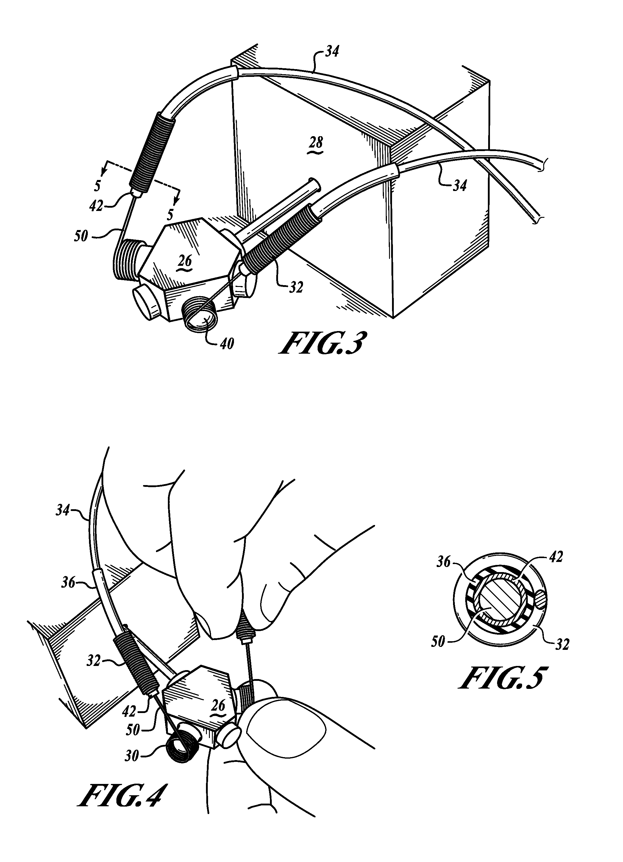
[0017]Before testing of the LBA 26 begins, the torsional electrode connectors 20, 22 are retrieved from a storage seat 24 and attached to cathodes (or electrodes) 40 of the LBA 26. Each of the torsional electrode connectors 20, 22 includes a first end having a torsion spring 30. The remaining portion of the connectors 20, ...


PUM


Abstract

A laser block assembly (LBA) gas fill process device with improved cathode electrode connectors. An example device includes a gas fill component that attaches to an LBA under test and electrical connectors that receive a voltage bias from a voltage source and apply the voltage bias to cathodes of the LBA. The electrical connectors include an end having a torsion spring that is sized based on the cathodes of the LBA. Also, the electrical connectors may include a strain relief spring.

Description

BACKGROUND OF THE INVENTION[0001]When a laser block assembly (LBA), such as LBA-1308 produced by Honeywell International Inc., is mounted to a gas fill process device, a voltage source is applied to cathodes of the LBA. FIG. 1 illustrates a ceramic plate device that is mounted onto the LBA. The ceramic plate device includes metallic loops that make an electrical contact with the cathodes of the LBA. Wires that connect the loops to the voltage source are attached to a second side of this ceramic plate and are bonded to the loops within the plate. After an LBA is mounted to a fill device, the ceramic block is placed on the LBA. After the fill process is complete, the ceramic plate is returned to a storage position. Because of both the high temperatures employed and the manipulation required mounting and demounting leadwires of the connector, assemblies have a tendency to fail prematurely. In addition, the brittle ceramic plate is subject to damage over the course of normal use.SUMMARY...

Claims


Application Information

Patent Timeline
Patent Type & Authority Patents(United States)
IPC IPC(8): H01R13/33
CPCH01R4/14H01R13/5804H01R13/33H01R2201/20Y10T137/7733
Inventor BAXTER, JAMES K.BOWMAN, ROBERT M.LILLEMO, KENNETH W.MEISSNER, LLOYD C.
Owner HONEYWELL INT INC
Why Eureka
Try Eureka