Acoustic coupling for assessment and ablation procedures

a technology of acoustic coupling and ablation, which is applied in the field of catheters, can solve the problems of reducing the accuracy of the assessment, the assessment is not readily determined using conventional fluoroscopy techniques, and the difficulty of detecting the damage of the surrounding tissue, so as to reduce the damage to the surrounding tissue, reduce the contact pressure, and increase the contact pressure

Inactive Publication Date: 2017-11-02
ST JUDE MEDICAL ATRIAL FIBRILLATION DIV
View PDF7 Cites 1 Cited by
  • Summary
  • Abstract
  • Description
  • Claims
  • Application Information

AI Technical Summary

Benefits of technology

[0007]In exemplary embodiments, a plurality of acoustic transducer elements are configured as one of the following: a one-dimension array, a two-dimension array, a three-dimensional array, a geometric shape, a sphere, and a cylinder. Also in exemplary embodiments, an acoustic transducer is configured to generate a canceling effect of acoustic energy at a desired distance to reduce or eliminate damage to surrounding tissue or anatomical structures.
[0008]In other exemplary embodiments, the system may further comprise a shielding device or fabricated harrier structures) to generate a canceling effect of acoustic energy at a desired distance to reduce or eliminate damage to surrounding tissue or anatomical structures. The shielding device can be positionable within or adjacent to an anatomical structure. For example, the shielding device can be insertable into or outside of the heart (e.g., endocardially or into the pericardial space) or esophagus (e.g., via the oral cavity or via one or more minimally invasive surgical incisions, “MIS” herein). In one example, the shielding device can be cylinder-shaped or spatula-shaped to facilitate use within or adjacent to the heart or esophagus. The shielding device can be relatively rigid or flexible and / or porous (e.g., sponge-like). Expandable and collapsible structures are also contemplated for use with the present invention apparatus and methods. Of course more than one shielding device can be deployed, via catheter delivery and / or MIS, during a procedure. The shielding device could also be a ‘hybrid structure’ that focuses or cancels energy in one region and merely blocks or deflects energy from another region. For example, a flat bottomed bowl-shaped structure or a partially flat-sided cylinder or half-pipe could accomplish both for energy impinging on either opposing major surface as could a spatula-like cannula. Therefore, as used herein, the term ‘shielding device’ means one or more structures configured for insertion into a body, such as a chamber of a heart, a pericardial space, an esophagus, or into position near or on organs or target or non-target tissue within the thoracic cavity that at least one [or both] of reflecting applied energy (e.g., causes a desired cancellation or focus of energy) and deflecting or blocking the energy from reaching non-target tissue.
[0011]Also disclosed are systems and methods for determining a level of contact between a catheter and tissue based on the acoustic signals. Other assessments may include determining tissue properties including, for example, the following: tissue depth, number of tissue layers, tissue interfaces, and tissue type. Also disclosed are systems and methods and devices for generating a canceling effect of acoustic energy at a desired distance to reduce or eliminate damage to surrounding tissue or anatomical structures. Although the systems and methods may utilize the acoustic energy for assessment purposes (e.g., when acoustic energy transmitters are used with conventional ablation electrodes), the acoustic energy may also be delivered to the tissue for lesion formation. In exemplary embodiments, the acoustic energy can be focused for lesion formation at a predetermined tissue depth.
[0012]Output can be stored in a memory structure and / or conveyed to the user in near real-time (e.g., at a display device or other interface) so that the user can properly position the catheter on the target tissue with the desired level of contact for the ablation procedure. For example, the user may increase contact pressure if the output indicates insufficient contact. Or, for example, the user may reduce contact pressure if the output indicates too much contact. Also, the user can be provided with, for example, a map of the tissue and / or surrounding anatomical structures to facilitate determining the position of the catheter relative to the tissue or surrounding anatomical structures. The user may also be provided with ablation formation information, e.g., indicating whether a sufficient ablative lesion has been formed.

Problems solved by technology

Several difficulties can be encountered, however, when attempting to form lesions at specific locations using some existing ablation electrodes.
One such difficulty encountered with existing ablation catheters is how to assess the tissue and catheter contact with the tissue.
These assessments are not readily determined using conventional fluoroscopy techniques.
Such experience only comes with time, and can be quickly lost if the physician does not use the catheter on a regular basis.
In addition, when forming lesions in a heart, the beating of the heart further complicates matters, making it difficult to assess and maintain sufficient contact pressure between the catheter and the tissue for a sufficient length of time to form a desired lesion.
If the contact between the catheter and the tissue cannot be properly maintained, a quality lesion is unlikely to be created.

Method used


Image

  • Acoustic coupling for assessment and ablation procedures
  • Acoustic coupling for assessment and ablation procedures
  • Acoustic coupling for assessment and ablation procedures

Examples


examples

[0100]The following are examples of other embodiments which are contemplated, and are provided for purposes of illustration, but are not intended to be limiting in any manner.

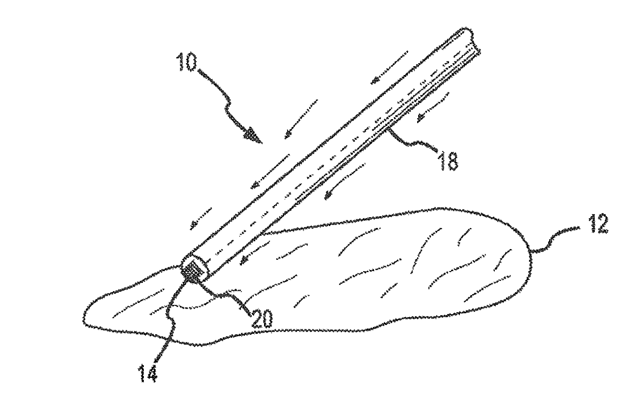
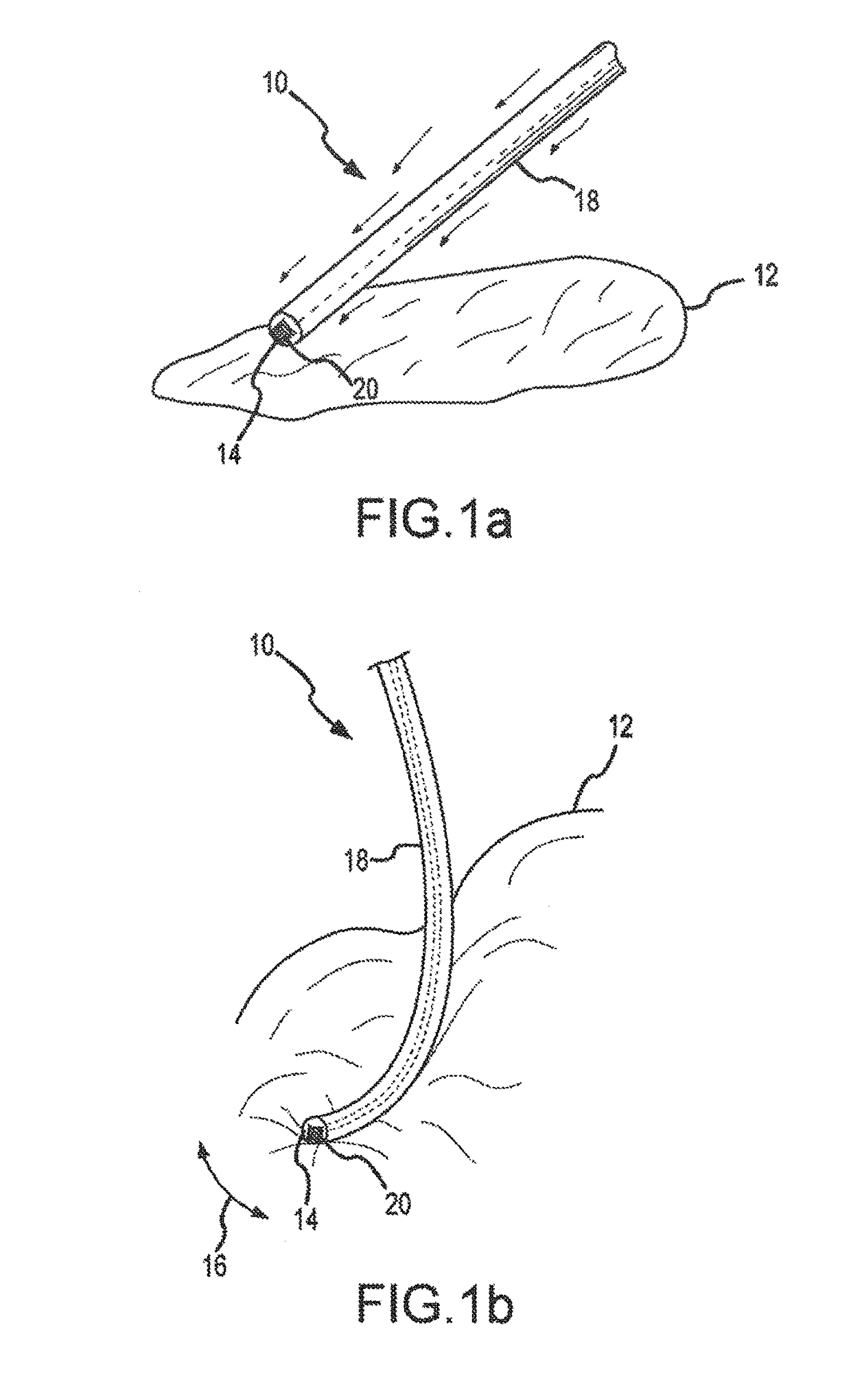
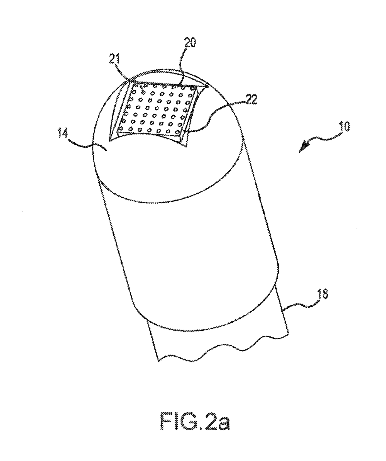
[0101]A method comprising: emitting acoustic signals from a catheter; receiving reflected acoustic signals at the catheter; and assessing a tissue based on the received acoustic signals.

[0102]The method, further comprising determining a level of contact between the catheter and the tissue based on the acoustic signals.

[0103]The method, further comprising reducing noise artifacts.

[0104]The method, further comprising simultaneously emitting and receiving the acoustic signals.

[0105]The method, further comprising alternating emitting and receiving the acoustic signals.

[0106]The method, further comprising generating a canceling effect of acoustic energy at a desired distance to reduce or eliminate damage to surrounding tissue or anatomical structures.

[0107]The method, further comprising assessing contact of the cath...


PUM


Abstract

Acoustic coupling systems and methods are disclosed as these can be used for assessment and ablation procedures. An exemplary acoustic assessment system for a catheter may comprise a flexible catheter shaft. At least one acoustic transducer is positioned in the flexible catheter shaft. The at least one acoustic transducer emits a generated acoustic signal for reflection by adjacent tissue. The at least one acoustic transducer receives a reflected acoustic signal from the adjacent tissue and generates electrical signals corresponding to one or more property of the tissue. An output device is electrically connected to the at least one acoustic transducer. The output device receives the electrical signals and generate output for a user for assessing the tissue.

Description

CROSS-REFERENCE TO RELATED APPLICATIONS[0001]This application is a continuation of U.S. application Ser. No. 12 / 979,475, filed 28 Dec. 2010 (the '475 application), now ______, which claims the benefit of U.S. provisional application No. 61 / 291,778, filed 31 Dec. 2009 (the '778 application). The '475 application and the '778 application are each hereby incorporated by reference as though fully set forth herein.BACKGROUND OF THE INVENTIONa. Field of the Invention[0002]The instant invention is directed toward a catheter and a method tier using the catheter for assessment and ablation procedures. In particular, the catheter of the present invention may comprise one or more acoustic transducers for assessment of tissue and / or for assessment of catheter contact with the tissue and / or for tissue ablation procedures.b. Background Art[0003]It is well known that benefits can be gained by forming lesions in tissue if the depth and location of the lesions being formed can be controlled. In part...

Claims


Application Information

Patent Timeline
Patent Type & Authority Applications(United States)
IPC IPC(8): A61N7/02A61B8/08A61B8/12A61B8/00A61B17/00
CPCA61B8/0883A61B8/12A61N7/022A61B8/4494A61B2017/00106A61B8/445
Inventor PAUL, SAURAVTEGG, TROY T.HEIMBECHER, REED R.
Owner ST JUDE MEDICAL ATRIAL FIBRILLATION DIV
Why Eureka
Try Eureka