
Stretching machine

a technology of stretching machine and stretching bar, which is applied in the field of stretching apparatus, can solve the problems of putting strain on muscles, lack of flexibility, etc., and achieve the effect of adding strengthening capabilities to the telescoping stretching bar and safe and effective stretching

Inactive Publication Date: 2005-03-10
DAVIES DAVID R III
View PDF9 Cites 13 Cited by
  • Summary
  • Abstract
  • Description
  • Claims
  • Application Information

AI Technical Summary

Problems solved by technology

Furthermore, lack of flexibility can lead to problems with the lower back, etc., as a person ages.
This method is particularly undesirable in a therapeutic environment since the full body weight often provides many times more force than is necessary or desired to accomplish the stretch, thus putting strain on the muscles.
Additionally, a patient in therapy often lacks the strength in their hands that is required to support their own body weight.
This machine is mechanically complex and extremely limited in the types of exercises and range of motions that can be accomplished.
For example, this type of machine cannot be used in a therapeutic environment where the patient has a back injury and is physically unable to bend at the torso.
Additionally, since it is a user operated motorized machine, that is actually stretching the muscles, it would be easy for an inexperienced or overzealous user to go too far and cause muscle hyperextension or some other unhealthy result.
Unfortunately, the stretch machines only allow the user to assume a straight-out, bent over posture and do not permit side-to-side movements or vertical stretch movements, which simulate hanging.
Unfortunately, the stretch machines only allow the user to assume a straight-out, bent over posture and side-to-side stretching is limited by the leg flexibility of the user.

Method used


Image

  • Stretching machine
  • Stretching machine
  • Stretching machine

Examples


Embodiment Construction

[0110] The following detailed description is of the best presently contemplated modes of carrying out the invention. This description is not to be taken in a limiting sense, but is made merely for the purpose of illustrating general principles of embodiments of the invention.

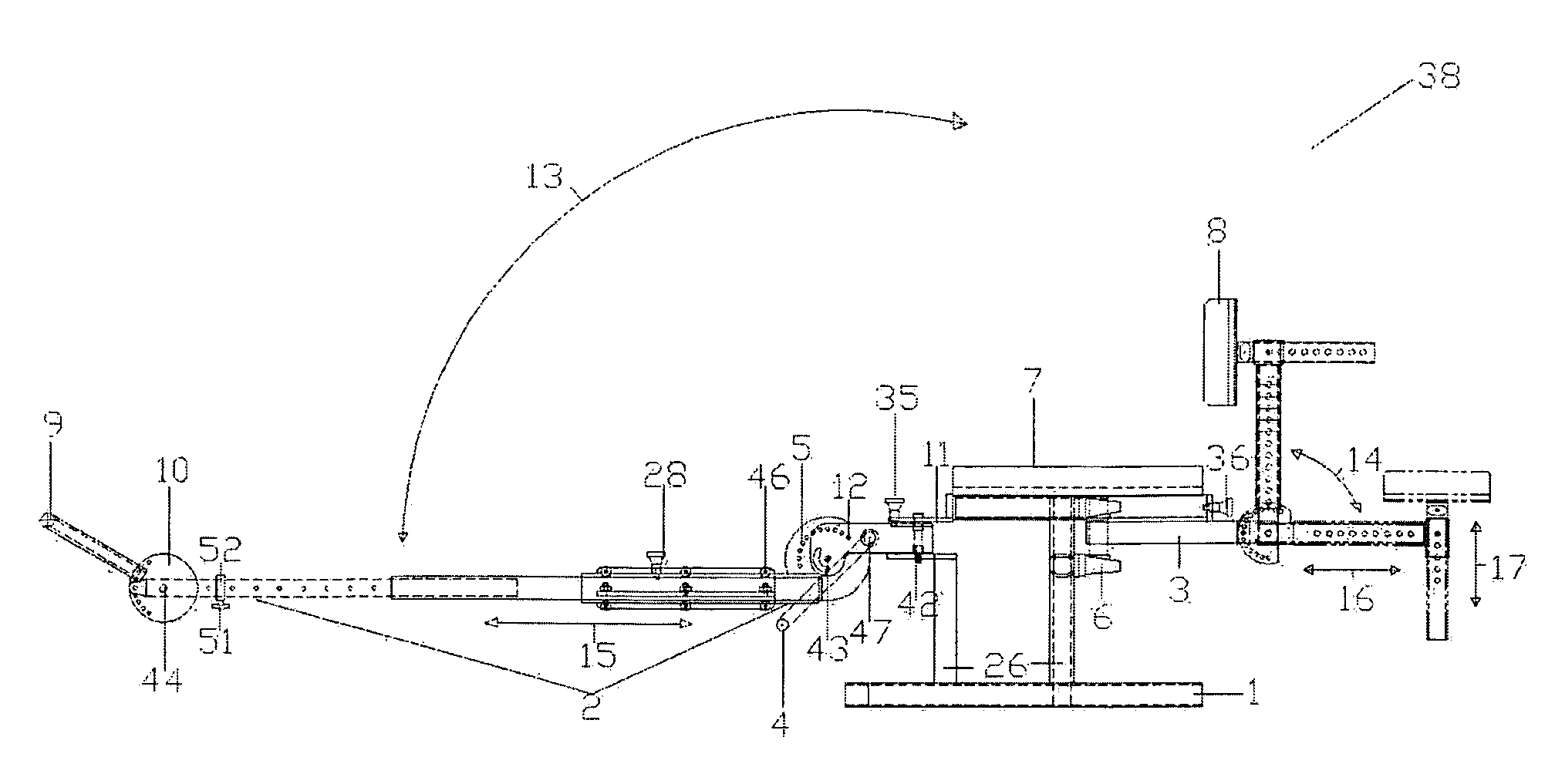
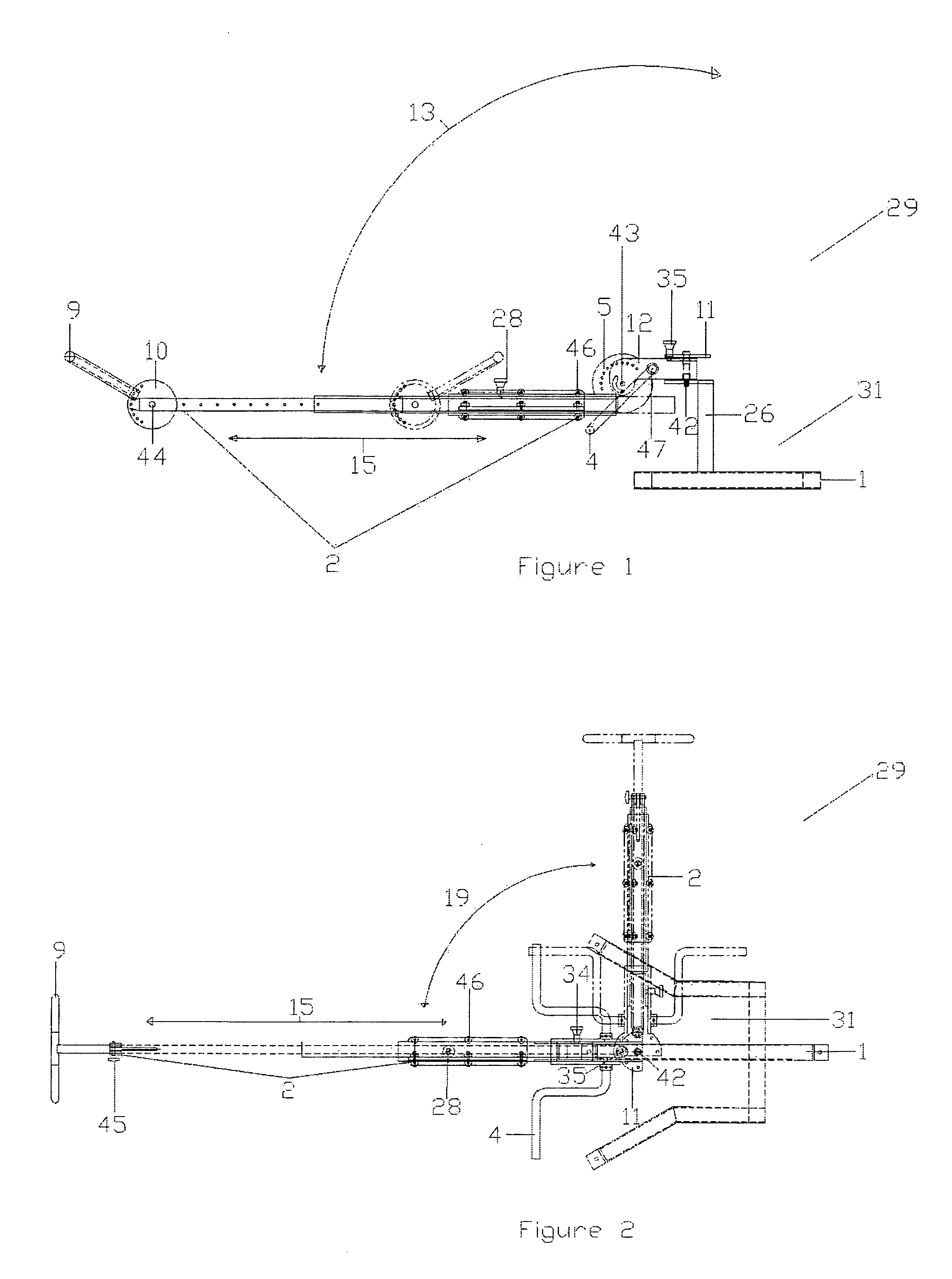
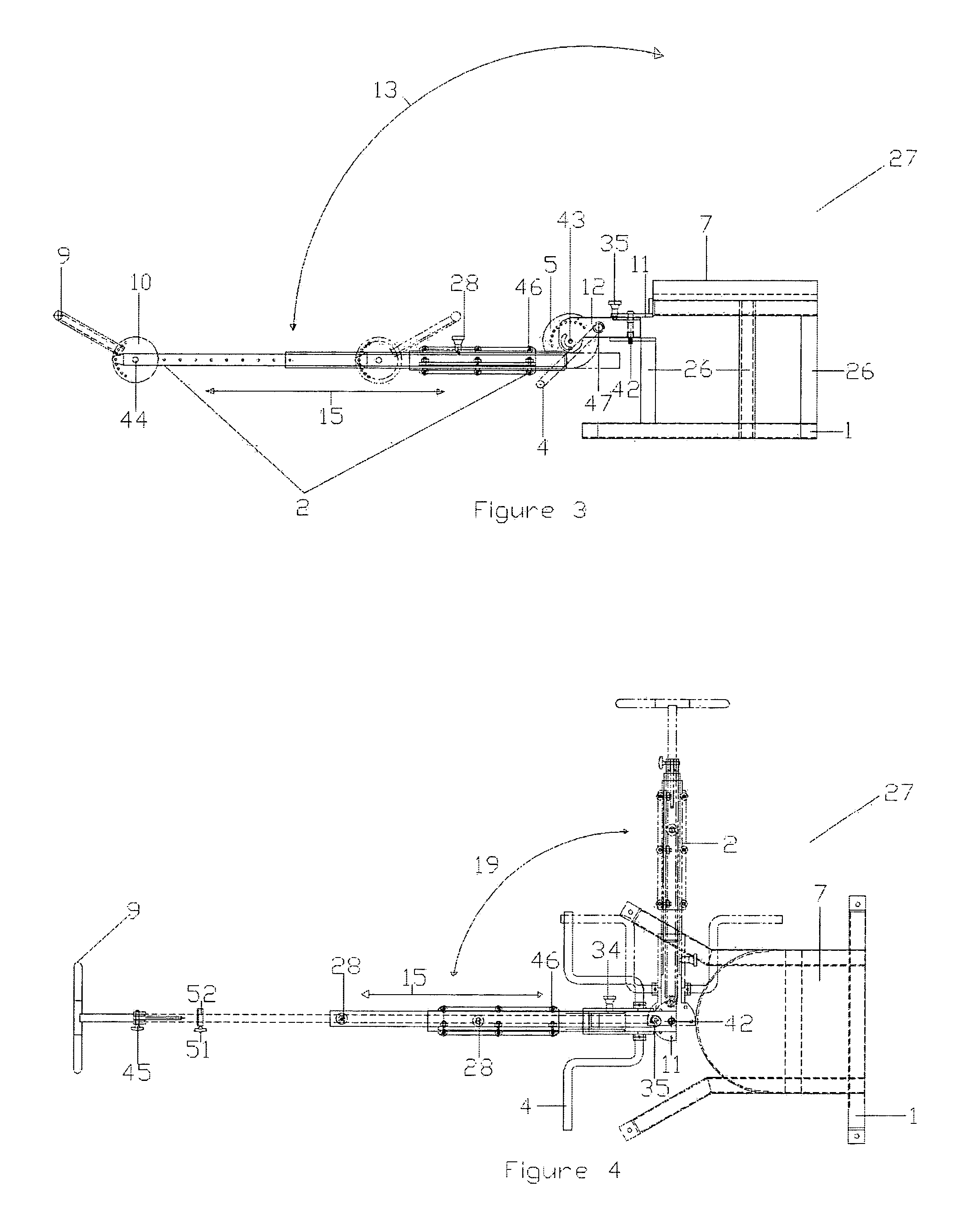
[0111] Referring now to the drawings, and more particularly to FIGS. 1 and 2, there are shown side and top views of the stretching machine generally referred to by the reference numeral 29. The support frame of the stretching machine is comprised of a base 1 which contains a single or multiple vertical support members 26 which are preferably made from tubular steel or a similar sturdy material of any desired cross-section, for example, round, square, U-shaped, or other appropriate shape. In the preferred embodiment, the telescoping stretching bar assembly 32 (shown in additional detail in FIGS. 19 and 20) consists of three nesting sections 48, 49, 50 and attaches to a vertical support member 26 of the base 1. I...


PUM


Abstract

A stretching machine that can be used for rehabilitation, medical treatment and fitness for paraplegics and athletes. The stretching machine is comprised of a stretching bar and a base. The stretching machine allows the user to stretch while in a seated or standing position. The telescoping stretching bar includes a mechanism for allowing the user to sit and fully extend his arms either directly in front of his torso, directly above his head, or any angle in between. Positioning the telescoping stretching bar to either side of the user allows for arm and shoulder stretching. In addition, the telescoping stretching bar can pivot to an angular orientation with respect to the user's waist. By changing the angle of the telescoping stretching bar and the position of the bar, with respect to the seated user, the target muscle groups change. Because of its open design the stretching machine can be easily operated by the user or easily assisted by a therapist or trainer. The telescoping stretching bar of the stretching machine uses a series of telescoping tubes to achieve a greater length when being used and extended, than when collapsed and not in use.

Description

CROSS REFERENCE TO RELATED APPLICATIONS [0001] The present application claims priority from U.S. Provisional Application Ser. No. 60 / 500,293, filed Sep. 4, 2003.FIELD OF THE INVENTION [0002] The invention is generally related to an apparatus for safely facilitating stretching exercises and rehabilitation. More particularly, the invention is directed to a stretching apparatus that allows stretching of a wide variety of muscle groups without undue stress. DESCRIPTION OF RELATED ART [0003] A physically fit person is defined by a combination of strength, endurance, and flexibility. Many individuals concentrate on strength and endurance by engaging in activities such as weight lifting and jogging, but ignore the need to be flexible. However, it is widely recognized by experts in the field that stretching prior to commencing an exercise regimen is of paramount importance to reduce the likelihood of exercise related injuries. Furthermore, lack of flexibility can lead to problems with the l...

Claims


Application Information

Patent Timeline
Patent Type & Authority Applications(United States)
IPC IPC(8): A61HA61H1/02A63B3/00
CPCA61H1/0229
Inventor DAVIES, DAVID R. III
Owner DAVIES DAVID R III
Learn More