
Baler plunger drive load measurement pin offset from either connecting rod center line or horizontal mid-plane of baling chamber

a technology of baler and plunger, which is applied in the field of baler, can solve the problems of data loss and increase cos

Active Publication Date: 2005-03-17
DEERE & CO
View PDF5 Cites 27 Cited by
  • Summary
  • Abstract
  • Description
  • Claims
  • Application Information

AI Technical Summary

Benefits of technology

An object of the invention is to provide a plunger load sensing arrangement which makes it possible to use one size of load sensing pin for various baler sizes.

Problems solved by technology

Data resolution is lost if a more robust load pin is used than is required for the loads that occur.
Consequently, a manufacturer that makes various sizes of balers is required to keep an inventory of load pins of various sizes, which increases cost.

Method used


Image

  • Baler plunger drive load measurement pin offset from either connecting rod center line or horizontal mid-plane of baling chamber
  • Baler plunger drive load measurement pin offset from either connecting rod center line or horizontal mid-plane of baling chamber
  • Baler plunger drive load measurement pin offset from either connecting rod center line or horizontal mid-plane of baling chamber

Examples


second embodiment

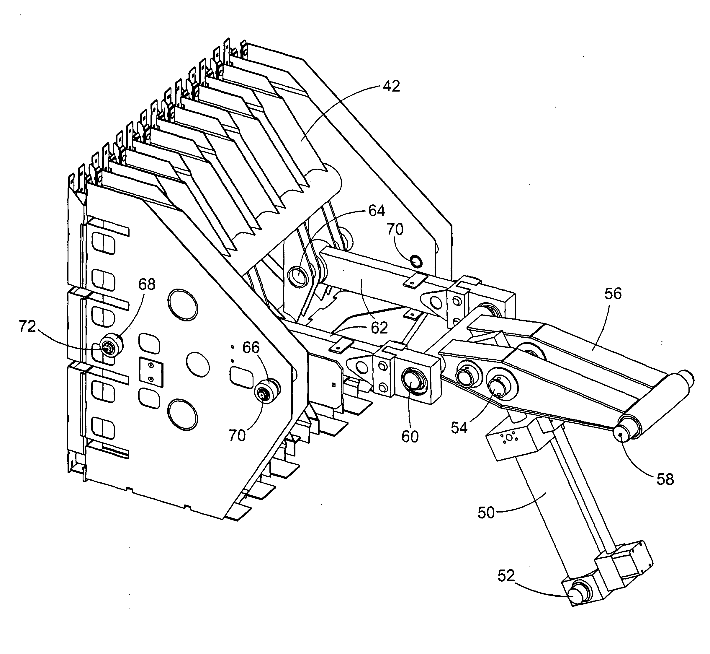
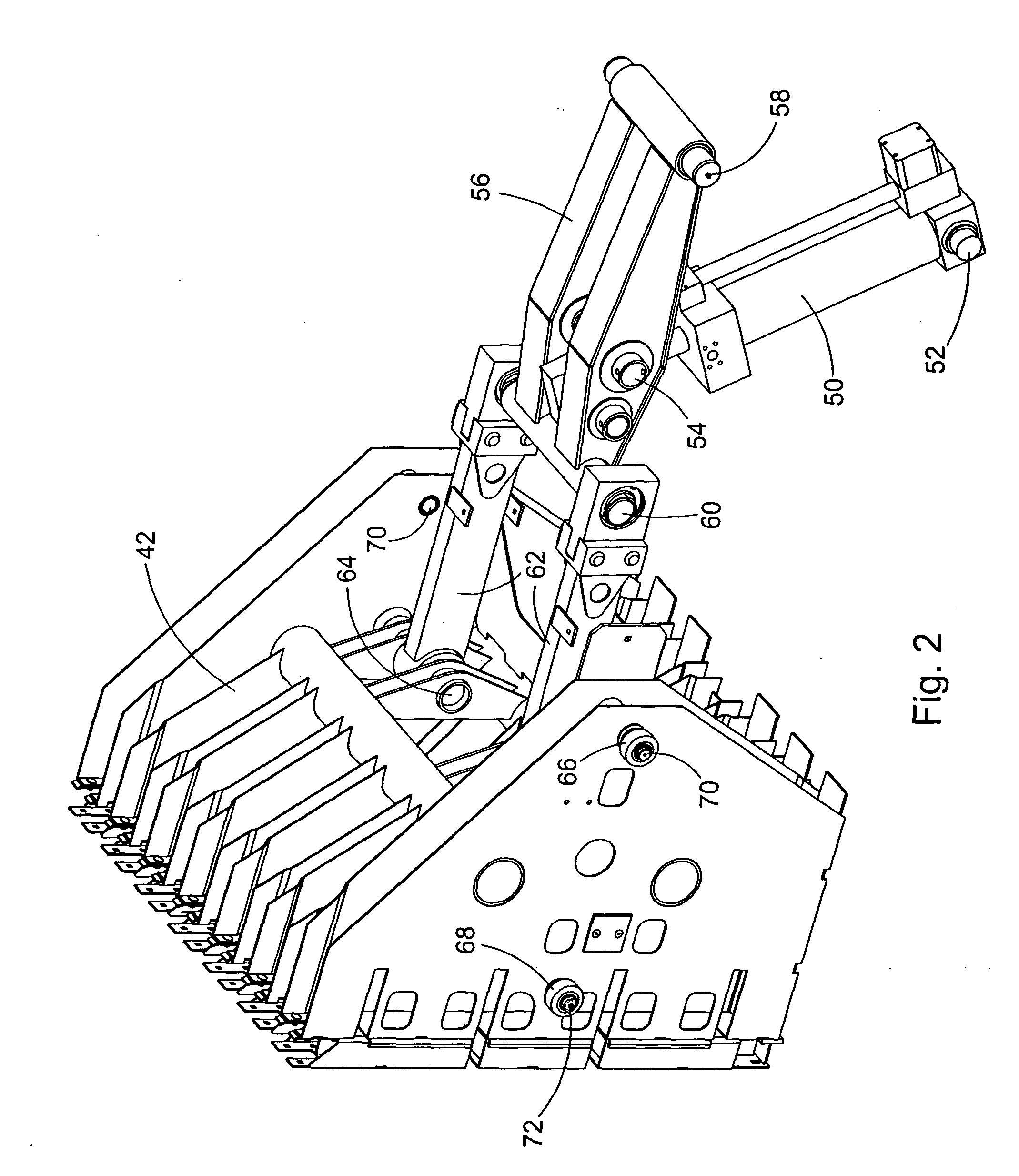
Referring now to FIG. 5, there is shown the invention. Specifically, illustrated is a plunger 42′ including right- and left-hand identical, transversely spaced plates, with only the left-hand plate 86 being visible. The plate 86 is here shown in the form of an equilateral triangle, with two corners being disposed in vertical alignment with each other and equally offset vertically on opposite sides of the central plane C, and with the remaining corner being located ahead of the other two corners and centered on the central plane C. The right- and left-hand triangular plates are respectively received between right- and left-hand pairs of plate-like, vertical strengthening ribs of the plunger 42′, with only the left-hand pair of ribs 88 being visible. A left-hand load pin 90L extends through aligned holes provided in the pair of ribs 88 and a bushing 92 forming an upper rear corner of the triangular plate 86, with it to be understood that a right-hand load pin 90R (not visible) is simi...

first embodiment

It is here noted that whether or not the plates coupling the connecting rods to the plunger 42′ are triangular is immaterial, but what is material is the locations of the load pins and coupling pins since the load computations are easier if these locations are similar to the triangular pattern shown. Like the connecting rods 62 of the first embodiment, the front ends of the connecting rods 62′ are pivotally coupled to the rear end of the crank arm 56 by the pin 60.

Referring now to FIG. 6, there is shown the left-hand triangular plate 86 showing the forces imposed thereon during a compaction stroke, with it to be understood that similar forces will be imposed on the right-hand triangular plate.

The following calculations, together with the free-body forces illustrated in FIGS. 5 and 6, demonstrate a concept to determine both side-to-side and vertical offset loading on the plunger of a baler while using only two load pins. There are four sensors, namely, a crank angle position senso...


PUM

PropertyMeasurementUnit
forceaaaaaaaaaa
densityaaaaaaaaaa
compaction forceaaaaaaaaaa

Abstract

A baler for making large parallelepiped bales includes a plunger drive and plunger arrangement wherein one or more load pins are located offset vertically from a centerline of a connecting rod or a mid-plane of the baling chamber. Such an arrangement permits load pins having the same range of measuring capacity to be used with balers of different sizes, with the amount of offset being changed for balers of different sizes. In one arrangement, load pins are offset vertically from the mid-plane of the plunger a distance sufficient to make it possible to measure differences in top-to-bottom reaction forces imposed on the plunger.

Description

FIELD OF THE INVENTION The present invention relates to balers for making large parallelepiped bales, and more specifically, relates to devices for measuring the load imposed by the baler plunger drive on a bale being formed so as to obtain a control signal used in forming uniform density bales. BACKGROUND OF THE INVENTION Balers for forming large parallelepiped bales are often equipped with a pre-compression chamber in the form of a curved chute or duct in which crop material is accumulated until it reaches a predetermined density whereupon a stuffer arrangement is actuated to lift the charge of crop material into the baling chamber at a location just behind the baler plunger. Once the charge of crop material is in the baling chamber, the plunger operates to compact the charge against previously compacted crop material located in the baling chamber and acting against the restriction of adjustable side panels which adjust the cross section of the baler to restrict the movement of ...

Claims


Application Information

Patent Timeline
Patent Type & Authority Applications(United States)
IPC IPC(8): A01F15/04A01F15/08A01F15/10
CPCA01F15/042A01F15/0825Y10T74/2142Y10T403/553Y10T29/49288A01F15/101
Inventor ROTH, DARIN LEDRU
Owner DEERE & CO
Features
  • Generate Ideas
  • Intellectual Property
  • Life Sciences
  • Materials
  • Tech Scout
  • Unparalleled Data Quality
  • Higher Quality Content
  • 60% Fewer Hallucinations
Learn More