Reel unit for a dual bearing reel

Active Publication Date: 2005-03-17
SHIMANO INC
View PDF7 Cites 28 Cited by
  • Summary
  • Abstract
  • Description
  • Claims
  • Application Information

AI Technical Summary

Benefits of technology

[0009] An object of the present invention is to make it possible to reliabl

Problems solved by technology

Here, by forming the annular member and the plate member of the first side plate separately, and by forming the annular member in which the female threaded portion is formed from a metal that is harder than the electrodeposition layer, it w

Method used


Image

  • Reel unit for a dual bearing reel
  • Reel unit for a dual bearing reel
  • Reel unit for a dual bearing reel

Examples


Embodiment Construction

[0037] Selected embodiments of the present invention will now be explained with reference to the drawings. It will be apparent to those skilled in the art from this disclosure that the following descriptions of the embodiments of the present invention are provided for illustration only and not for the purpose of limiting the invention as defined by the appended claims and their equivalents.

[0038] According to the present invention, the side cover can be reliably coupled to a side plate of a reel unit of a dual bearing reel by forming an annular member that has a female threaded portion in a first side plate, the female threaded portion being formed with a hardened electrodeposition layer, and by forming a separate plate member from a magnesium alloy.

[0039] Overall Configuration

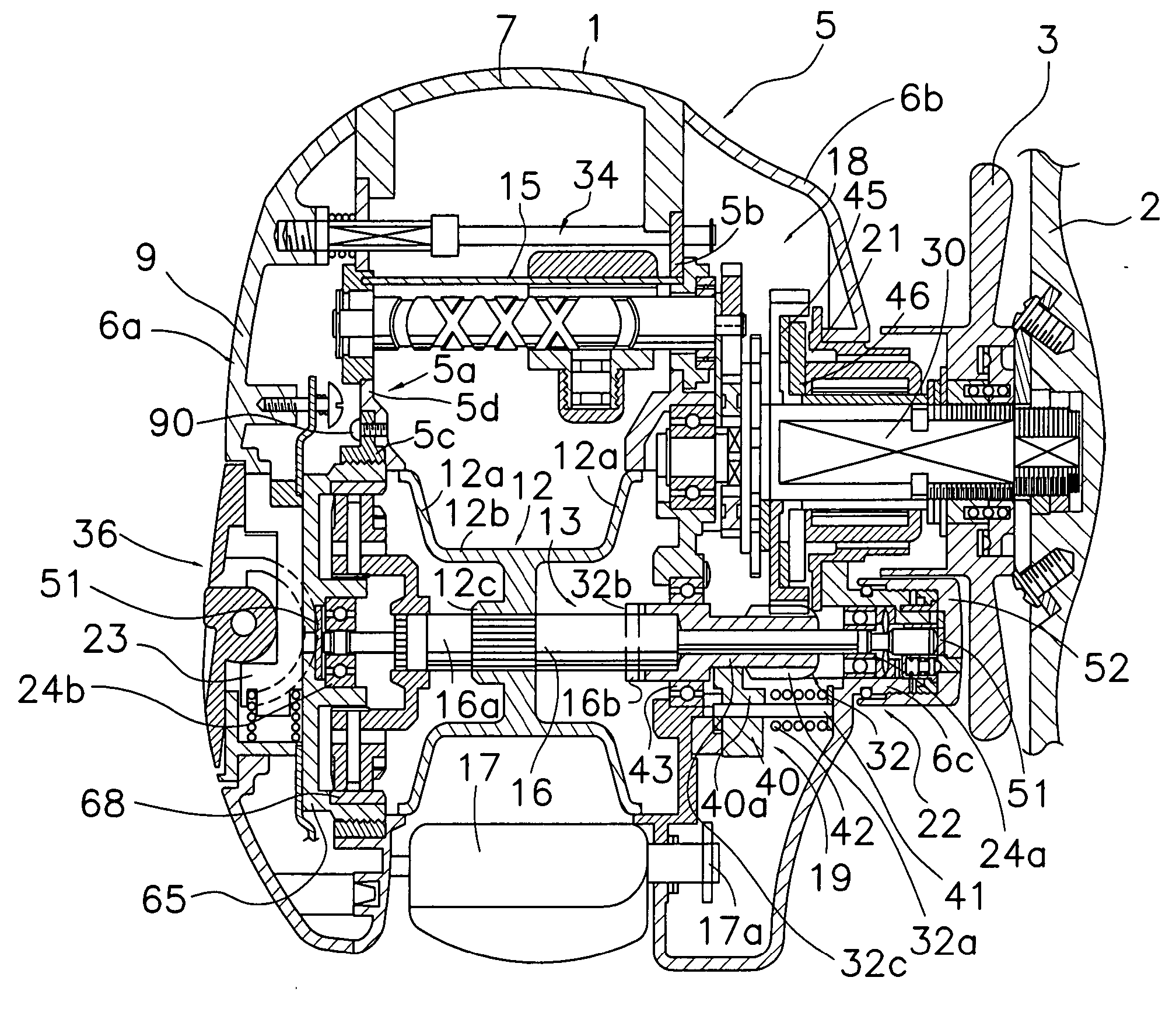
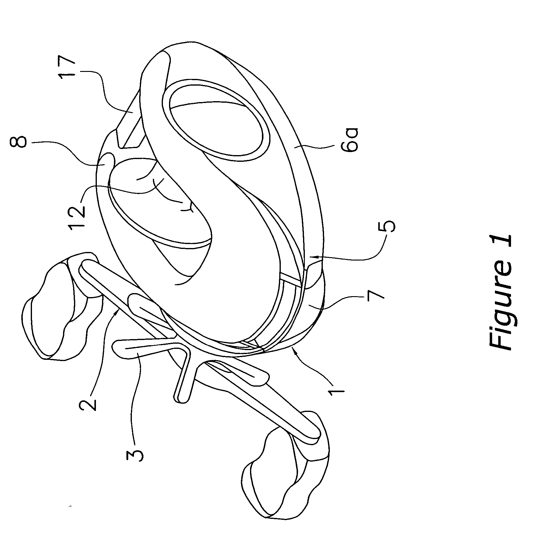
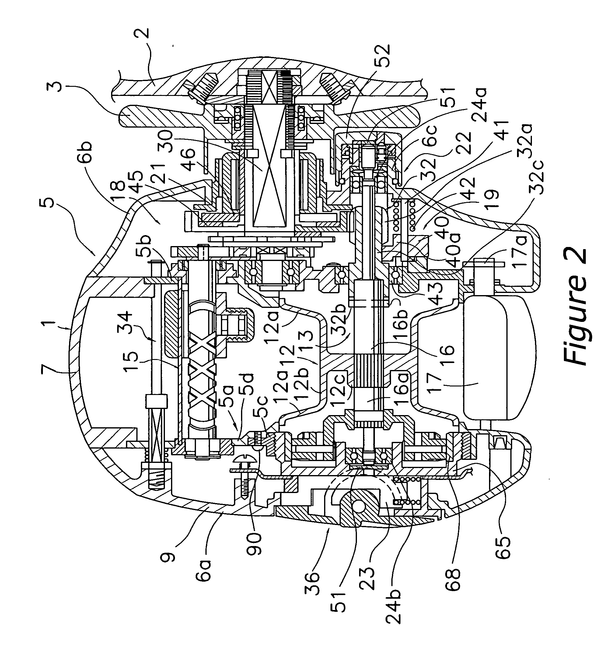
[0040] As shown in FIG. 1, a dual bearing reel according to an embodiment of the present invention has a low profile and is used for bait casting. This dual bearing reel includes a reel unit 1, a handle 2 t...


PUM


Abstract

A reel unit includes a frame, and first and second cover plates that are detachably mounted on both sides of the frame. The frame includes first and second side plates and a plurality of connectors that connect the first and second side plates. The first side plate includes a plate member and an annular member. The plate member includes a first opening in its inner peripheral portion. The plate member is made of a magnesium alloy, with an ellectrodeposition treatment being performed on a surface of the plate member. The annular member has a second opening through which the spool is adapted to pass, and a female threaded portion that is formed on an inner peripheral portion of the second opening. The annular member is harder than the surface of the plate member on which the electrodeposition treatment is performed.

Description

BACKGROUND OF THE INVENTION [0001] 1. Field of the Invention [0002] The present invention relates to a reel unit. More specifically, the present invention relates to a reel unit for a dual bearing reel on which a spool for winding line that is rotated by a handle can be detachably mounted. [0003] 2. Background Information [0004] Generally, a dual bearing reel includes a reel unit that is mounted on a fishing rod, a spool that is rotatively mounted on the reel unit, and a handle that serves to rotate the spool. The handle is rotatively mounted on one side of the reel unit, and is connected to the spool via a gear mechanism. The reel unit includes a frame and a pair of side covers. The frame includes a pair of left and right side plates and connection members that connect both of the side plates, and the pair of side covers covers both sides of the frame. An opening through which the spool is capable of passing is provided in the side plate opposite the side plate on which the handle ...

Claims


Application Information

Patent Timeline
IPC IPC(8): A01K89/00A01K89/015
CPCA01K89/015A01K89/00A01K89/01921A01K89/01557A01K89/01912
Inventor KAWASAKI, KEN'ICHI
Owner SHIMANO INC
Why Eureka
Try Eureka