
Vehicle seat of retractable type

a retractable type, vehicle seat technology, applied in the direction of movable seats, dismountable/non-movable seats, transportation and packaging, etc., can solve the problems of manual retractable vehicle seats that encounter a great and troublesome labor on the user's side, deterioration of usability and workability of seats, and link mechanisms disposed forward of seats

Inactive Publication Date: 2005-03-17
TACHI S CO LTD
View PDF9 Cites 37 Cited by
  • Summary
  • Abstract
  • Description
  • Claims
  • Application Information

AI Technical Summary

Benefits of technology

[0007] In view of the above-stated drawbacks, it is a first purpose of the present invention to provide an improved vehicle seat of retractable type which permits for automatic smooth displacement of the seat between a high use position and a low storage position in a manner analogous to a manual operation by person.
[0019] It is a second purpose of the present invention to avoid increase of a torque of the motor of the foregoing drive means.

Problems solved by technology

However, this kind of manually retractable vehicle seat encounters a great and troublesome labor on the user's side because of a relatively heavy weight of the seat and a too narrow space surrounding the seat in which the user has to move the seat to either of the use and storage positions.
Apparently, a lot of troublesome operations are required in this particular manual retractable seat, thereby resulting in a great degradation of usability and workability of the seat.
But, if such powered arrangement is applied to the above-stated prior-art seat, the link mechanism disposed forwardly of the seat will be a technical obstacle against operation of a motor in order to realize smooth movement of the seat to either of the use and storage positions in a manner analogous to manual operation by person.
To overcome this difficulty will involve a complicated structure and mechanism and increase costs accordingly.

Method used


Image

  • Vehicle seat of retractable type
  • Vehicle seat of retractable type
  • Vehicle seat of retractable type

Examples


Embodiment Construction

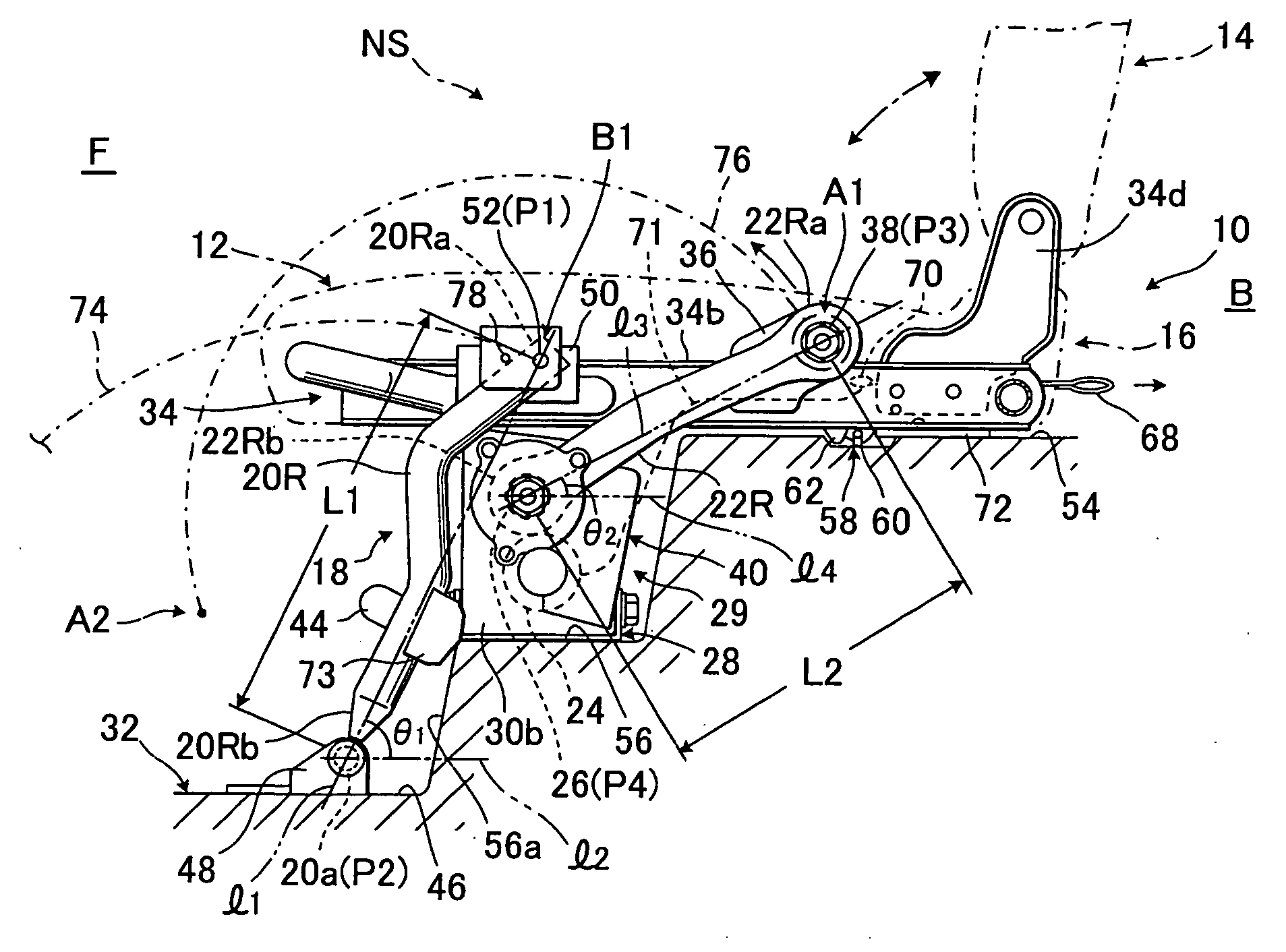
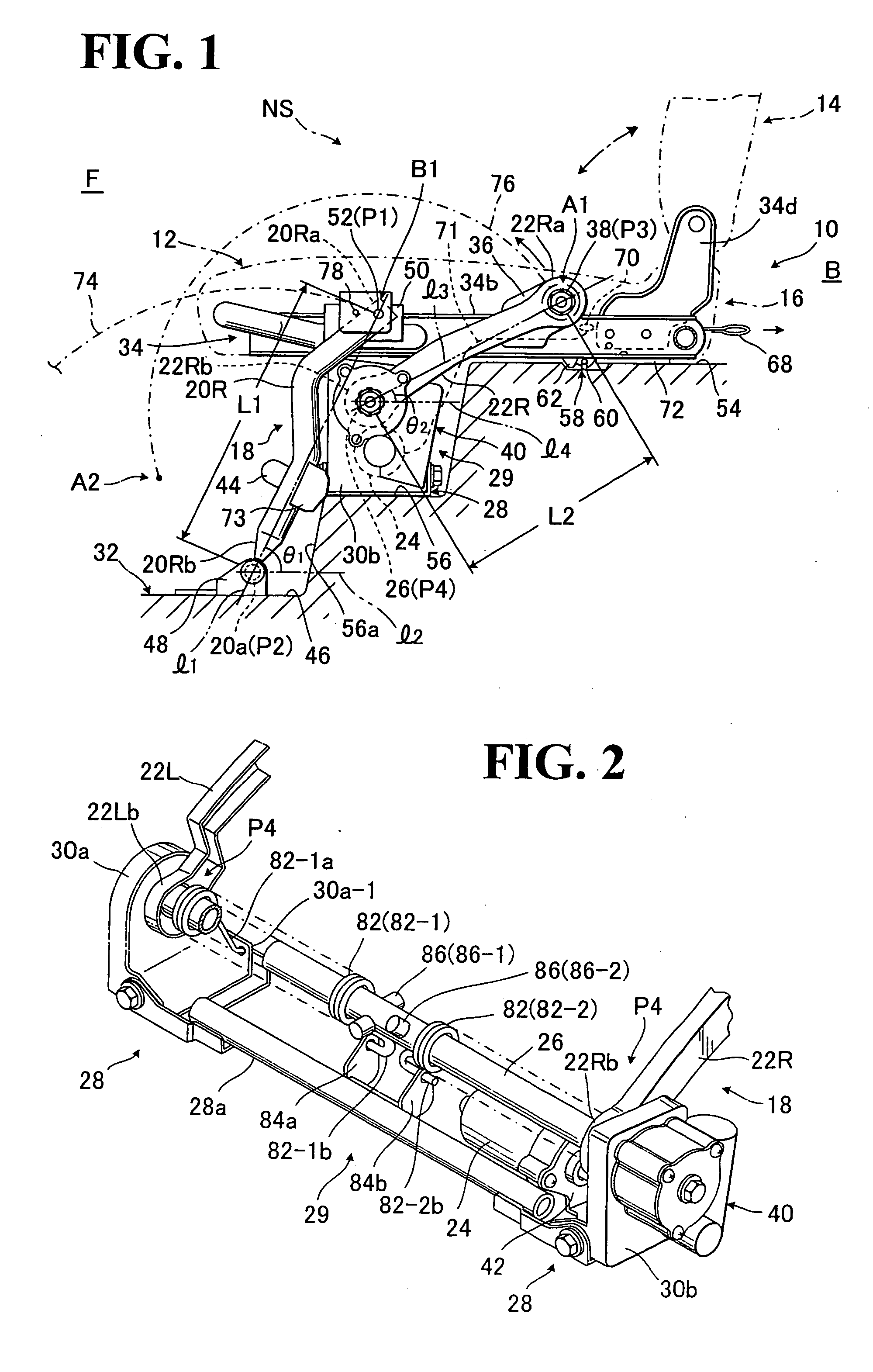
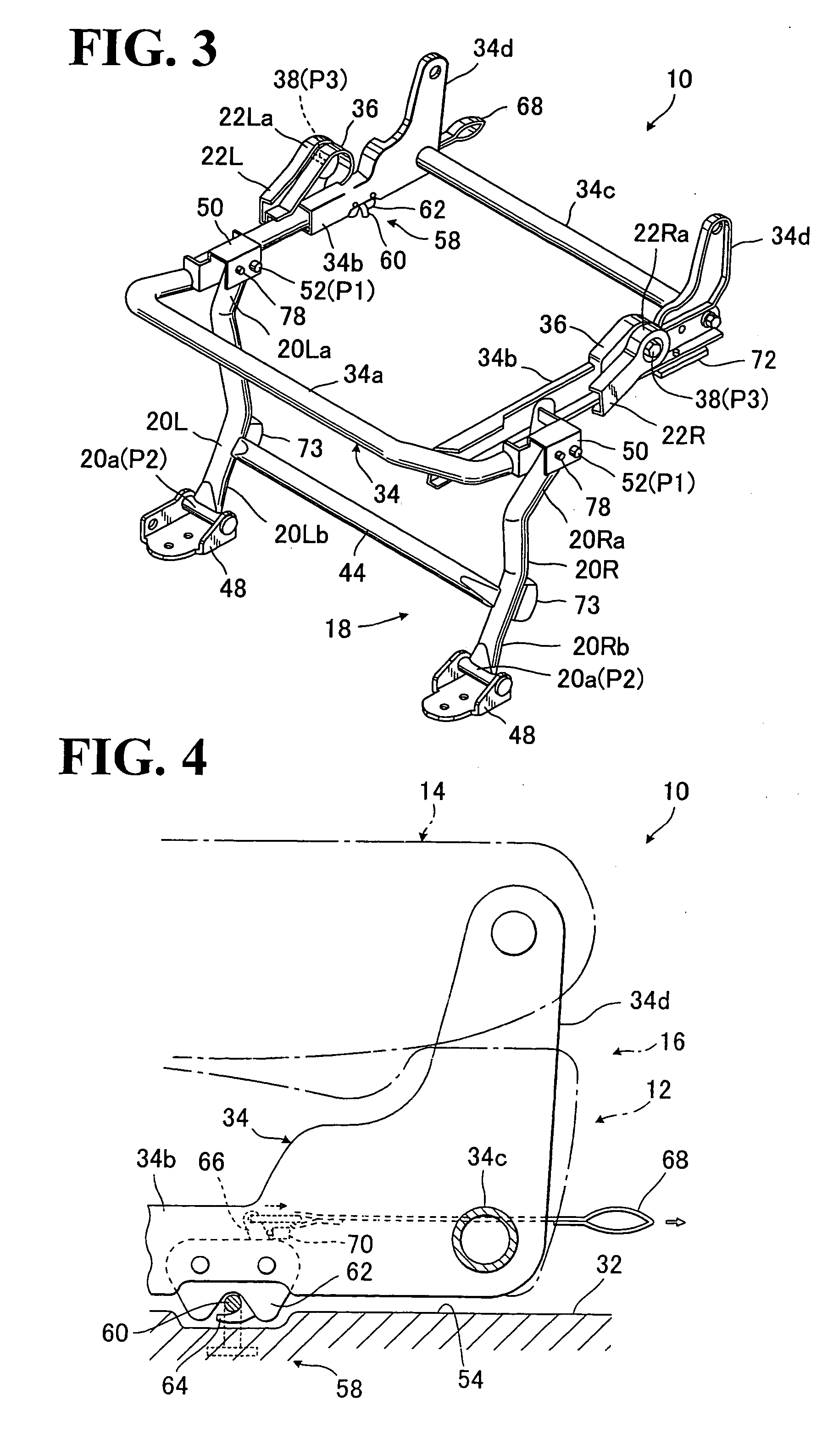
[0034] Referring to FIGS. 1 through 12(C), there is illustrated one preferred embodiment of powered seat of retractable type for use in a vehicle or automobile, generally designated by (10), in accordance with the present invention.

[0035] As shown in FIG. 1, the seat (10) includes a seat cushion (12) and a seat back (14) as a basic seat unit designated by (16) to facilitate the ease of understanding of description hereinbelow.

[0036] As is known, the seat cushion (12) is normally set in a generally horizontal use position, while the seat back (14) is set at an upright use position, hence providing a normal unfolded state of the basic seat unit (16) as indicated by one-dot chain lines and designation (NS) in FIG. 1. On the other hand, the seat back (14) is foldable onto the seat cushion (12), with the back side (14a) of the former (14) being exposed outwardly and laying on a substantially horizontal plane, hence providing a folded state of the basic seat unit (16) as indicated by tw...


PUM


Abstract

Vehicle seat of retractable type having a rotary support link mechanism, which is displaceable between upper use position and lower storage position. The rotary support link mechanism comprises a forward link element and a backward link element smaller in length than the forward link element, wherein the forward link element has upper and lower pivotal support points between the seat and a vehicle floor, while the backward link element has upper and lower pivotal support points between the seat and vehicle floor. The lower pivotal support point of the backward link element is disposed backwardly of and above the lower pivotal support point of the forward link element, and the backward link element is inclined more backwardly than the forward link element. With this arrangement, the seat can be displaced by operation of motor between the upper use position and lower storage position in a manner analogous to a manual operation.

Description

BACKGROUND OF THE INVENTION [0001] 1. Field of the Invention [0002] The present invention relates to a vehicle seat of retractable type which allows a seat back to be folded onto a seat cushion and further allows both seat back and seat cushion to be rotated donwardly from an upper use position to a lower storage position close to a point where a seat occupant's feet rest on, so that a whole of the seat can be retracted and stored in the storage position. [0003] 2. Description of Prior Art [0004] Most of conventional retractable vehicle seats, as disclosed in the Japanese Laid-Open Patent Publication No. 2000-108745 for instance, are operable manually to fold and move both seat back and seat cushion to a storage position. According to such prior art, a seat cushion is rotatably provided on an upper area of a floor where the seat itself is set in a normal use position, i.e. a use position, and also movably supported by a link mechanism disposed forwardly of the seat, which extends fr...

Claims


Application Information

Patent Timeline
IPC IPC(8): B60N2/015B60N2/30
CPCB60N2/01583B60N2/0232B60N2/309B60N2/3065B60N2/3011B60N2/02246
Inventor HATTA, SUSUMUTSUKADA, MITSURU
Owner TACHI S CO LTD
Learn More