
Enhanced cursor control using interface devices

a cursor control and interface technology, applied in the field of interface devices, can solve the problems of inability to physically accomplish the target acquisition task for users, insufficient or even harmful large scaling of mouse movement to cursor movement, and difficulty in adjusting the target acquisition mode, so as to reduce the sense of mapping mode change, enhance the control of the cursor, and reduce the offset

Inactive Publication Date: 2005-03-17
IMMERSION CORPORATION
View PDF99 Cites 17 Cited by
  • Summary
  • Abstract
  • Description
  • Claims
  • Application Information

AI Technical Summary

Benefits of technology

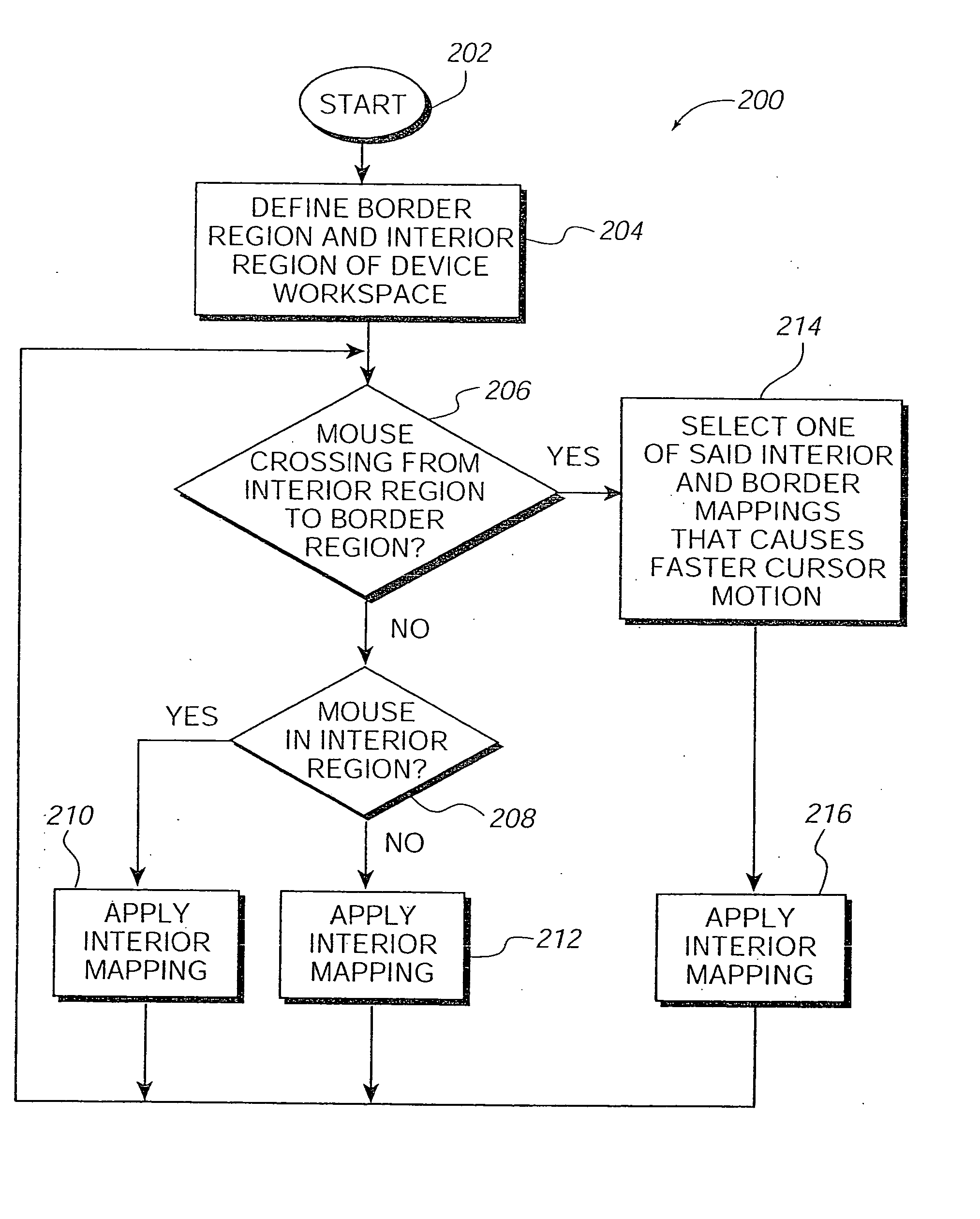
In one embodiment, when the mouse moves from the interior region to the border region, the mapping providing the greater cursor velocity is used to decrease any sense of mapping mode change to the user. In a different embodiment, the force feedback device performs auto-centering of the manipulandum in its workspace using the actuators of the device to decrease an offset between the local frame and the screen frame.

Problems solved by technology

However, a problem occurs when the user wishes to move the cursor a short distance or in small increments (“fine positioning”).
For tasks in which accurate positioning of the cursor is needed, such as target acquisition tasks, the large scaling of mouse movement to cursor movement is inadequate or even harmful.
Certain target acquisition tasks where the targets are very small can be particularly challenging even if the mapping between the cursor and the mouse is reasonable for most other cursor motion activities.
For such situations, a scaling that causes large motions of the cursor for small motions of the mouse may make a target acquisition task physically impossible for the user.
Mouse ballistics and other mappings may cause difficulty in certain fixed-workspace force feedback mouse implementations.
If this offset becomes too large, the user may not be able to reach some parts of the screen within the range of motion of the mouse.
However, some types of force feedback mice may have a fixed, limited workspace due to cost and technological constraints and may not be able to be lifted off the table and repositioned.
In addition, the mouse hitting a physical limit to its workspace is disconcerting for a user expecting realistic force feedback.
Thus, traditional indexing (or its equivalent) may not be practical.

Method used


Image

  • Enhanced cursor control using interface devices
  • Enhanced cursor control using interface devices
  • Enhanced cursor control using interface devices

Examples


Embodiment Construction

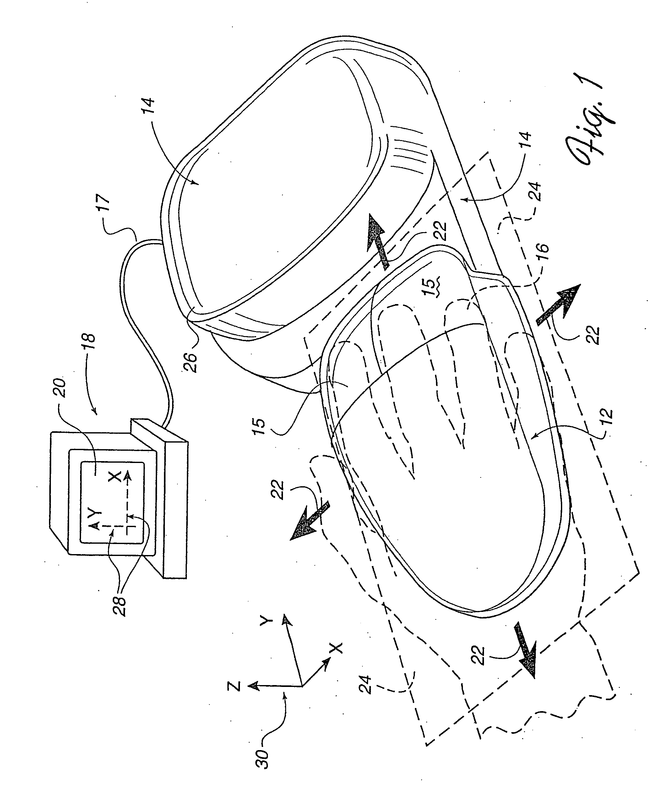
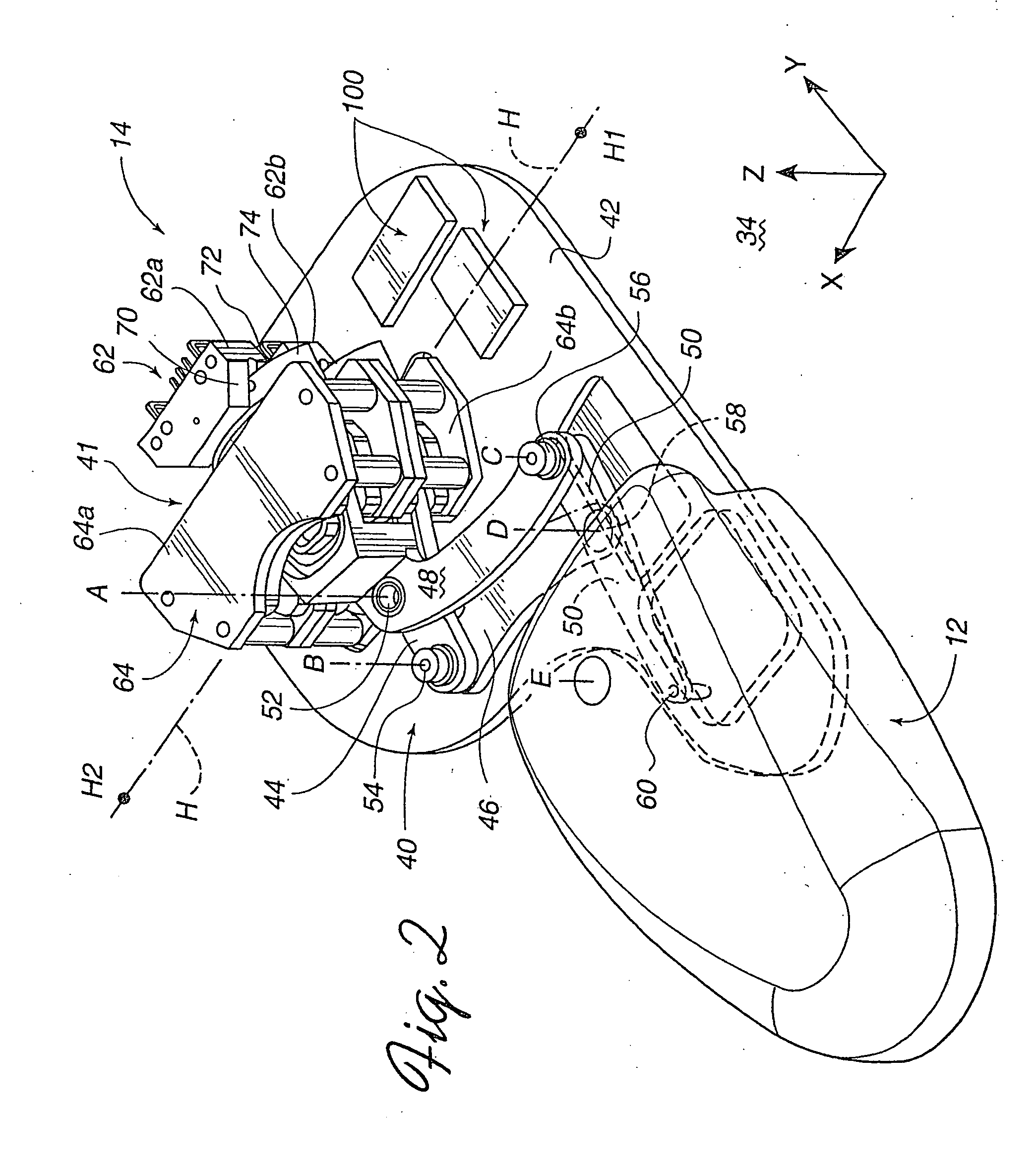
FIG. 1 is a perspective view of a force feedback mouse interface system 10 of the present invention capable of providing input to a host computer based on the user's manipulation of the mouse and capable of providing force feedback to the user of the mouse system based on events occurring in a program implemented by the host computer. Mouse system 10 includes a mouse or “puck”12, an interface 14, and a host computer 18. It should be noted that the term “mouse” as used herein, indicates an object 12 generally shaped to be grasped or contacted from above and moved within a substantially planar workspace (and additional degrees of freedom if available). Typically, a mouse is a smooth or angular shaped compact unit that snugly fits under a user's hand, fingers, and / or palm, but may be shaped otherwise in other embodiments.

Mouse 12 is an object that is preferably grasped or gripped and manipulated by a user. By “grasp,” it is meant that users may releasably engage a portion of the objec...


PUM


Abstract

An interface device and method for providing enhanced cursor control with force feedback. A force feedback interface device includes a manipulandum, such as a mouse, that is moveable in a local workspace. The device is coupled to a host computer that displays a cursor in a graphical environment, such as a GUI, on a display screen. An interior region and a border region in the local workspace is defined. One mapping of device movement to cursor movement is used for the interior region, and a different mapping is used for the border region. Mapping methods include ballistics, absolute, linear, rate control, and variable absolute. Rate control embodiments can be single axis or dual axis. In one embodiment, when the mouse moves from the interior region to the border region, the mapping providing the greater cursor velocity is used to better conserve device workspace in the direction of travel and to decrease any sense of mapping mode change to the user. Other features include an autocentering function for reducing offset between local and host frames.

Description

BACKGROUND OF THE INVENTION The present invention relates generally to interface devices for allowing humans to interface with computer systems, and more particularly to computer interface devices that allow the user to provide input to computer systems and provide force feedback to the user. Graphical environments are commonly displayed on computer systems. One visual environment that is particularly common is a graphical user interface (GUI). The user typically moves a displayed, user-controlled graphical object, such as a cursor, across a computer screen and onto other displayed graphical objects or predefined screen regions, and then inputs a command to execute a given selection or operation. The objects or regions (“targets”) can include, for example, icons, windows, pull-down menus, buttons, and scroll bars. Most GUI's are currently 2-dimensional as displayed on a computer screen; however, three dimensional (3-D) GUI's that present simulated 3-D environments on a 2-D screen ...

Claims


Application Information

Patent Timeline
IPC IPC(8): G06F3/00G06F3/01G06F3/038G06F3/042
CPCG06F3/016G06F3/0354G06F3/03548G06F2203/015G06F3/0421G06F2203/014G06F3/038
Inventor MALLETT, JEFFREY R.CHANG, DEAN C.ROSENBERG, LOUIS B.BRAUN, ADAM C.MARTIN, KENNETH M.BEAMER, JONATHAN L.
Owner IMMERSION CORPORATION
Learn More