Scanning optical mouse

a mouse and optical technology, applied in instruments, cathode-ray tube indicators, computing, etc., can solve the problems of not providing the same level of precision and leveraging of existing components, and leveraging might not provide the same level of precision and leveraging

Inactive Publication Date: 2005-03-17
AGERE SYST INC
View PDF11 Cites 42 Cited by
  • Summary
  • Abstract
  • Description
  • Claims
  • Application Information

AI Technical Summary

Benefits of technology

[0017] The present invention allows users to perform quick scans of paper documents (or an image on some other physical surface) without requiring a separate, standalone scanner. The present invention does so by imparting scanning functionality to an optical mouse, such as a wireless optical mouse. The scanning sensor and / or the scanning light source could be same as that used for optical motion detection. Alternatively, a separate light source and / or imaging element could be provided in the body of the mouse for purposes of scanning.

Problems solved by technology

However, such an embodiment might not provide the same level of precision and leveraging of existing components as an embodiment using an optical positioning system.

Method used


Image

  • Scanning optical mouse
  • Scanning optical mouse
  • Scanning optical mouse

Examples


first embodiment

[0037]§ 4.1.2 First Embodiment

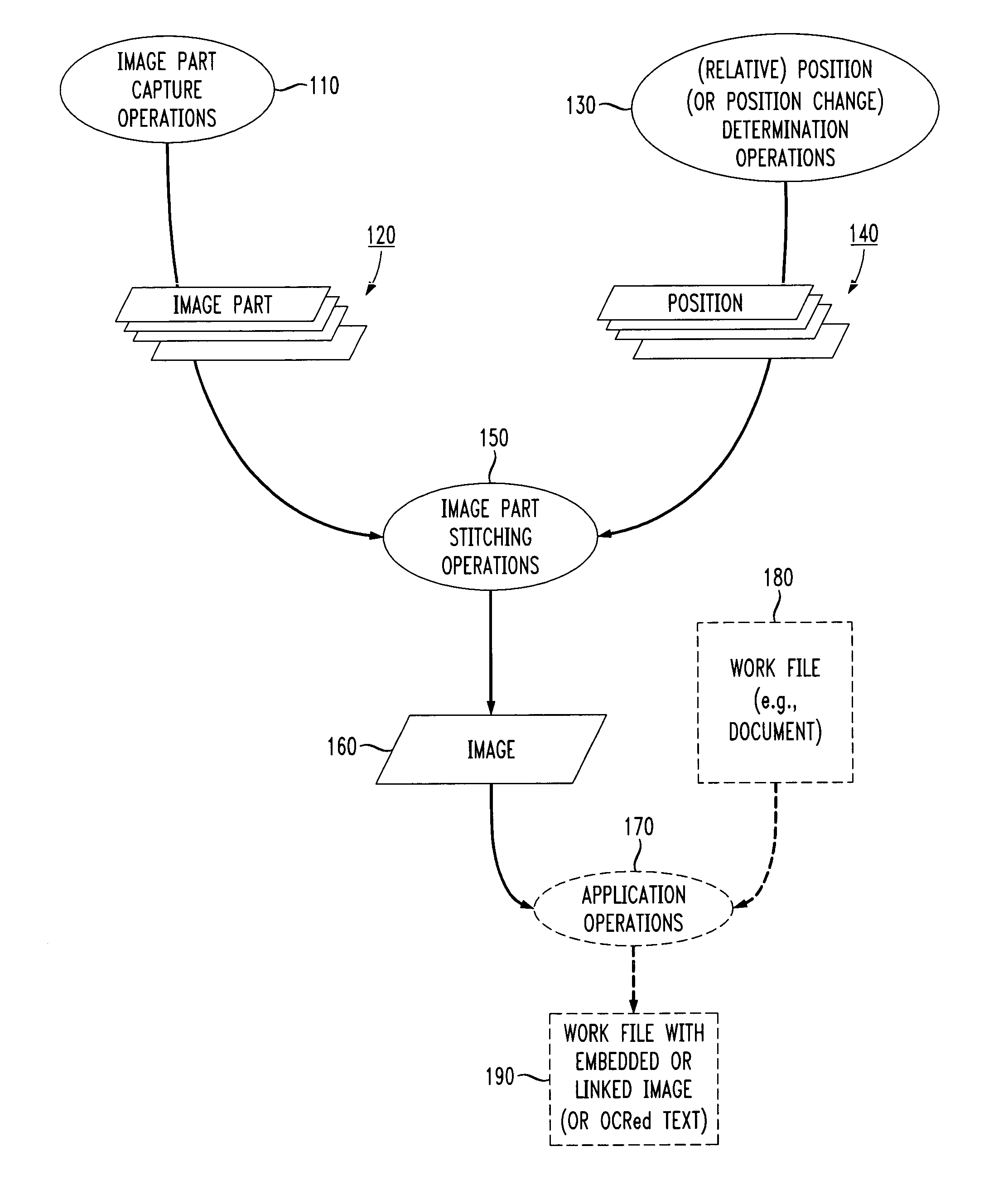
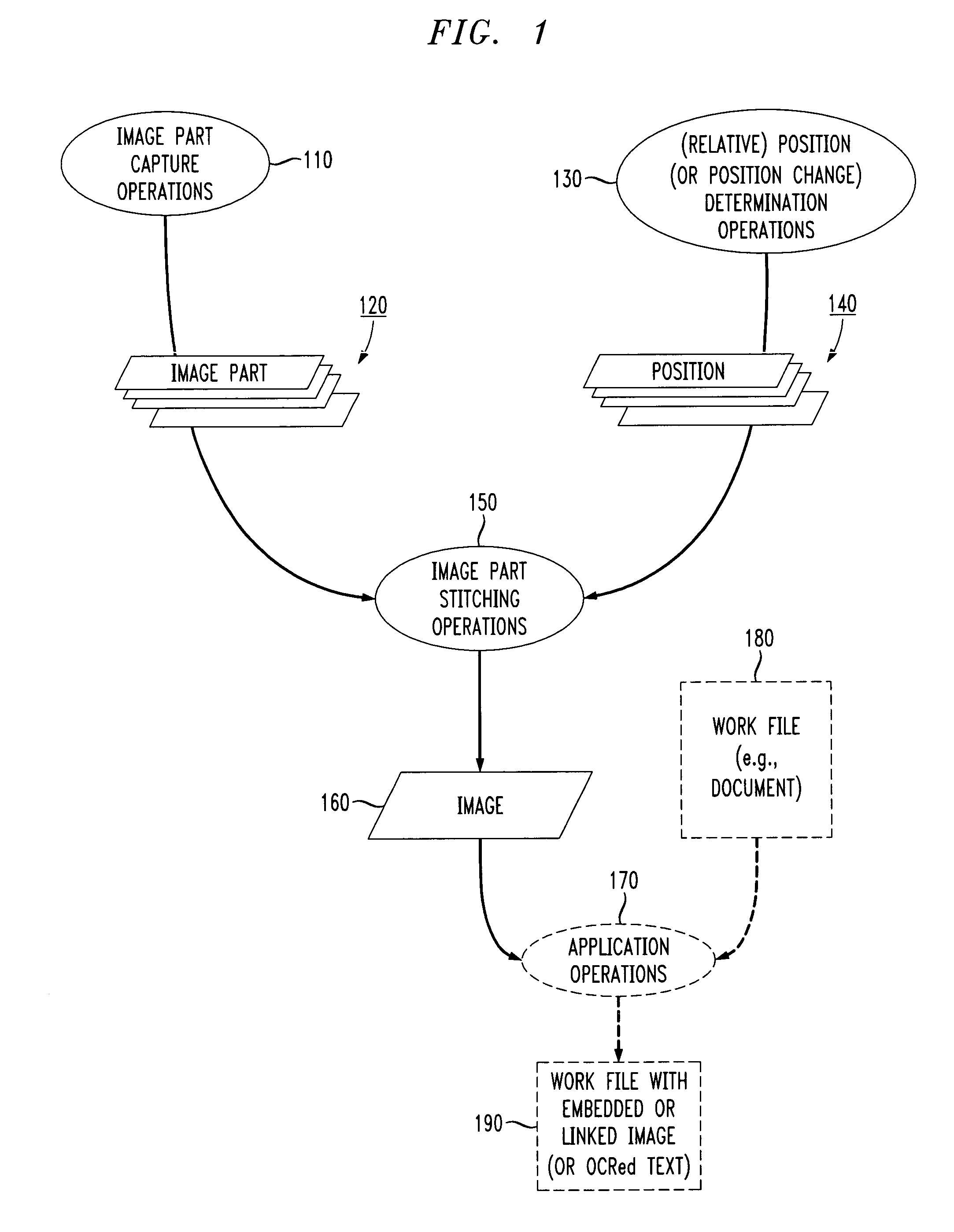
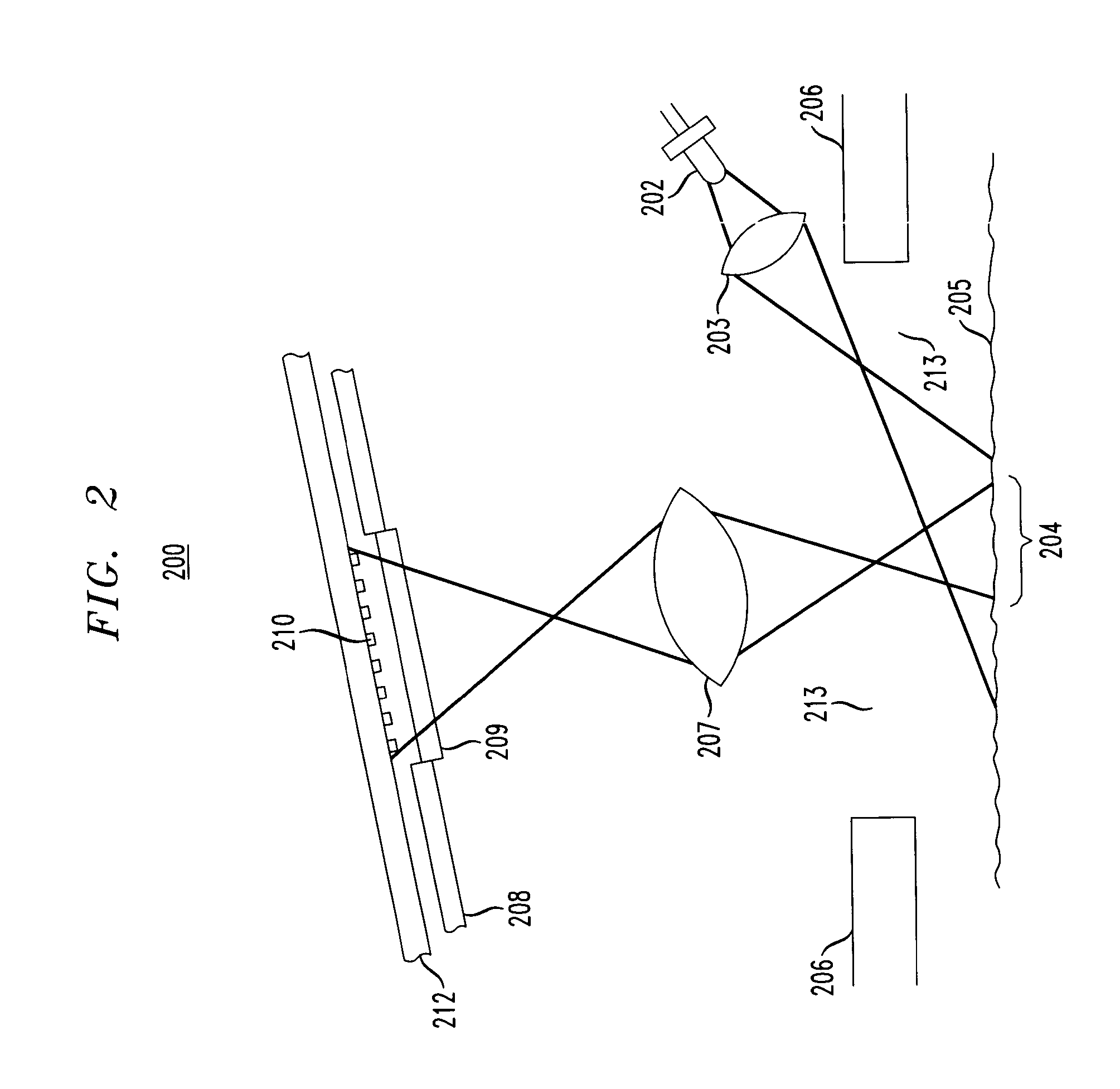
[0038]FIG. 2 is a diagram of a first exemplary embodiment 200 of the present invention. In the first embodiment 200, the image part capture operations 110 and position determination operation 130 share a light source and an image pickup device. A lens 203 projects light emitted from a light source (e.g., LED, IR LED, etc.) 202, through a window or opening 213 in a bottom surface 206 of a mouse and onto a region 204 that is part of a document (or some other surface having micro textures) 205 being scanned.

[0039] An image of illuminated region 204 is projected by lens 207 through an optical window 209 in package portion 208 of an integrated circuit and onto an imaging device (e.g., an array of photo detectors such as a CCD) 210. The window 209 and lens 207 may be combined. The imaging device 210 may comprise a 12-by-12 through 24-by-24 square array. Arrays having other shapes, sizes and resolutions are possible.

[0040] In this first embodiment 200, the l...

second embodiment

[0041]§ 4.1.3 Second Embodiment

[0042]FIG. 3 is a diagram of a second exemplary embodiment 300 of the present invention. The second exemplary embodiment 300 is similar to the first 200, but uses a separate light source 350 for illuminating a document (or some other surface being scanned) 305 for purposes of scanning. Light from the additional light source 350 may be projected onto the document (or some other surface) 305 being scanned at an angle of incidence greater than that of light source 302. A lens 360 may also be provided, but such a lens 360 is not strictly necessary. The light sources 302 and 350 may controlled to emit light in an alternating fashion—when light source 302 is emitting, captured images are used for position determination, while when light source 350 is emitting, captured images are used for image part capture (scanning).

third embodiment

[0043]§ 4.1.4 Third Embodiment

[0044]FIG. 4 is a diagram of a third exemplary embodiment 400 of the present invention. The third exemplary embodiment 400 is similar to the first 200, but uses a separate image pickup device 470 for purposes of image part capture (scanning) operations. Light reflected from the surface of the document (or other surface) 405 being scanned may be projected onto the separate image pickup device 470 using lens 480.

[0045] In one refinement of this embodiment 400, light emitted from the light source 402 may be made to hit the surface of the document (or some other surface) 405 at different angles of incidence—a smaller angle of incidence for purposes of position determination using imaging device 410, and a larger angle of incidence for purposes of image part capture (scan) using imaging device 470.

[0046] In an alternative or further refinement of this embodiment 400, the light source 402 may be made to emit different types (e.g., tuned or modulated wavelen...


PUM


Abstract

An optical mouse scanner allows users to perform quick scans of paper documents (or of some other surface) without requiring a separate, standalone scanner. Scanning functionality may be provided to an optical mouse, such as a wireless optical mouse. The scanning sensor and/or the scanning light source could be same as that used for the optical motion detection for the mouse. Alternatively, a separate light source and/or imaging element could be provided for purposes of scanning. Image stitching software could use a number of captured images (e.g., a stream of captured frames) alone, or in association with mouse orientation and/or position information, to assemble a larger image from smaller captured image frames.

Description

§ 1. BACKGROUND [0001]§ 1.1 Field of the Invention [0002] The present invention concerns scanning information from a hard copy. More specifically, the present invention concerns providing positioning (e.g., for moving a cursor on a display screen) and scanning functionality in a single unit. [0003]§ 1.2 Related Art [0004] The development and use of mice and scanners are introduced below in §§ 1.2.1 and 1.2.2, respectively. [0005]§ 1.2.1 The Development and Use of Mice [0006] With the advent of the graphical user interface (“GUI”), various devices for positioning a cursor on a display screen have been developed. The most popular of these has been the so-called “mouse.”[0007] Initially, conventional mice were mainly mechanical devices. A mechanical mouse typically has a bottom surface with downward projecting pads of a low friction material that function to raise the bottom surface a short distance above the work surface of a cooperating mouse pad, as well as a centrally located hole ...

Claims


Application Information

Patent Timeline
Patent Type & Authority Applications(United States)
IPC IPC(8): G06F3/03G06F3/033G06V10/22H04N1/00H04N1/047H04N1/107
CPCG06F3/0317G06F3/03543H04N2201/04787H04N2201/04712H04N2201/04703H04N1/107H04N1/047H04N1/00204G06K9/2054H04N2201/04737H04N2201/04743H04N2201/02439H04N2201/04794G06V10/22
Inventor BAINES, DONALD A.KELLER, JACK KRATZERRICHMAN, RUSSELL MARK
Owner AGERE SYST INC
Why Eureka
Try Eureka