Surveillance system and a surveillance camera

a surveillance camera and surveillance system technology, applied in the field of surveillance systems, can solve the problems of preventing further tracking, difficult to move or add surveillance cameras, and inability to track movable objects, so as to keep tracking of targets even

Active Publication Date: 2005-03-17
PANASONIC CORP
View PDF5 Cites 106 Cited by
  • Summary
  • Abstract
  • Description
  • Claims
  • Application Information

AI Technical Summary

Benefits of technology

According to the above-described surveillance system, a plurality of surveillance cameras communicate the feature information on a tracking target with each other, and each surveillance camera uses the feature information to track the target. This makes it possible to keep tracking of a target even in a space including more blind spots.

Problems solved by technology

Even when a plurality of cameras are used, a system that detects the motion of a movable object to determine a target camera, information about position and motion of the movable object is lost when a blind spot is present, thus preventing further tracking.
Therefore, in an environment where cameras can be seamlessly set up, such as in a wide place or complicated place, tracking of a movable object is impossible.
Therefore, it is not easy to move or add surveillance cameras.

Method used


Image

  • Surveillance system and a surveillance camera
  • Surveillance system and a surveillance camera
  • Surveillance system and a surveillance camera

Examples


first embodiment

A surveillance camera unit of a surveillance system of the first embodiment has a function to recognize a movable object (person) and a function to exchange information on a recognized person between the surveillance camera units.

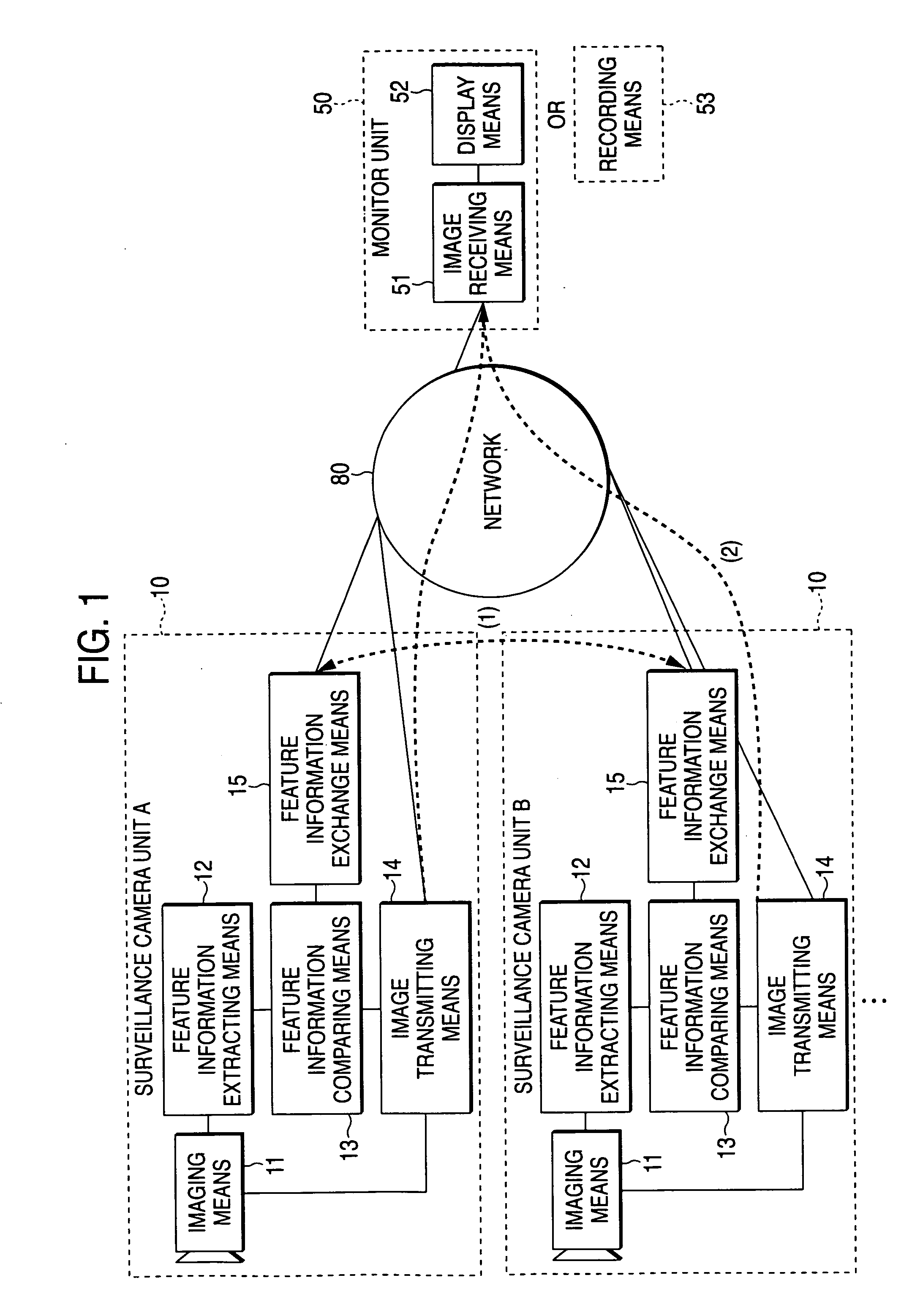
As shown in FIG. 1, the surveillance system has a plurality of surveillance camera units 10 and a monitor unit 50 for displaying images of a person under tracking transmitted from the surveillance camera units 10. Necessary data is transmitted via a network 80 between the surveillance camera units 10 and between the surveillance camera units 10 and the monitor unit 50.

The surveillance camera units 10 (surveillance camera unit A and surveillance camera unit B, for example) each has imaging means 11 for picking up images and outputting digital image data, feature information extracting means 12 for extracting feature information on the image picked up by the imaging means 11, feature information comparing means 13 for comparing the feature information ex...

second embodiment

The second embodiment is a surveillance system where a monitor unit can designate a tracking target.

The monitor unit 50 of the system has, as shown in FIG. 9, feature information exchange means 54 for exchanging feature information with the surveillance camera unit 10 and tracking target designating means 55 used by a surveyor to designate a tracking target. The remaining configuration is the same as that of the first embodiment (FIG. 1).

Operation of the surveillance system will be described referring to FIGS. 10A-10D.

A surveillance camera unit A in FIG. 10A which has extracted the feature information on a movable object transmits the image picked up by the imaging means 11 (FIG. 10B) to the monitor unit 50 from a image transmitting means 14. The image is received by the image receiving means 51 of the monitor unit 50, and the display means 52 displays the image.

A surveyor of the monitor unit 50, who has found a suspicious person from the image on the display, designates th...

third embodiment

The third embodiment is a surveillance system where a suspicious person other than those who are registered is tracked.

As shown in FIG. 11, this surveillance system has a user feature information database 70 where the feature information on registered users is stored. The remaining configuration is the same as that of the first embodiment (FIG. 1).

In the user feature information database 70, registered user list that describes information for uniquely enabling to identify a user, such as face image, information on position and shape of eyes, nose, mouth and so on regarding features of face, or iris information, is registered as the feature information of a user.

The feature information extracting means 12 of the surveillance camera unit 10 extracts the feature information from an image picked up by the imaging means 11. When feature information is input from the feature information extracting means 12, the feature information comparing means 13 acquires a registered user list ...


PUM


Abstract

The surveillance system is a system that a plurality of surveillance camera units cooperatively acquire image of a movable object. Each of the surveillance camera units is equipped with a image recognition function. A surveillance camera unit that has recognized the feature information on the movable object in the image picked up transmits the image to a monitor unit via a network and the feature information on the movable object to the other surveillance camera unit via the network. A surveillance camera unit that has recognized the feature information received from the other camera unit in the image picked up transmits the image to the monitor unit via the network as well as transmits the feature information on the movable object to the other surveillance camera unit via the network. This makes it possible to keep tracking of a target even in a space including more blind spots.

Description

BACKGROUND OF THE INVENTION 1. Field of the Invention The present invention relates to a surveillance system equipped with a plurality of surveillance cameras and a surveillance camera used in the system, particularly, to a surveillance system that performs surveillance of moving persons by way of combination of a plurality of cameras and a camera used in the system. 2. Description of the Related Art A variety of systems that performs automated surveillance of persons who enters or exits a building have been developed. “JP P2000-163600A1” discloses a surveillance system that extracts the characteristics of the face of a person from the image picked up by a surveillance camera and compares the characteristics with facemasks registered in a database. In this system, control means for analyzing an image signal from a surveillance camera recognizes the position of the face of a person shot by the surveillance camera and controls the panning, tilting and zooming operations of the sur...

Claims


Application Information

Patent Timeline
Patent Type & Authority Applications(United States)
IPC IPC(8): G08B13/196G08B25/00G08B25/04G08B25/10H04N7/18
CPCG08B13/19608G08B13/19641H04N7/181G08B25/009G08B13/19656G06V20/52
Inventor MARUYA, KENSUKE
Owner PANASONIC CORP
Why Eureka
Try Eureka