Radio transmitter and envelope tracking power supply control method

a technology of power supply control and radio transmitter, which is applied in the direction of amplifiers, antennas, electricly long antennas, etc., can solve the problems of power difference and large difference in occurrence probability of digitally modulated waves, and achieve the effect of higher pa

Inactive Publication Date: 2013-12-03
HITACHI LTD
View PDF8 Cites 28 Cited by
  • Summary
  • Abstract
  • Description
  • Claims
  • Application Information

AI Technical Summary

Benefits of technology

[0014]A plurality of voltage supplies are prepared. Then, a voltage is selected and output from the plurality of voltage supplies so that the power amplifier can operate at the max PAE with respect to the input signal. In this case, being more precise selection of the power supply voltage is an important factor in the improvement of the PAE of the power amplifier. This is because, as described with reference to FIG. 2, the power supply voltage at which the power amplifier operates at the max PAE varies depending on the input power. In the case of using the digitally modulated wave in which the input power typically varies, smoothly tracking the envelope of the input signal is ideal for obtaining the max PAE. Thus, in the ET power supply for outputting discrete voltage from a plurality of voltage supplies, it is possible to more accurately track the envelope of the input signal. In other words, the larger the number of voltages that can be selected, the more possible it is to approach the power supply voltage at which the PAE is the maximum in the power amplifier. As a result, the PAE is improved.
[0020]By controlling the ET power supply to output the voltage according to the signal power distribution, ET operation with higher PAE can be achieved.

Problems solved by technology

However, not only the power difference but also the difference in the occurrence probability is large in these digitally modulated waves.

Method used


Image

  • Radio transmitter and envelope tracking power supply control method
  • Radio transmitter and envelope tracking power supply control method
  • Radio transmitter and envelope tracking power supply control method

Examples


first embodiment

[0045]The configuration of a radio transmitter will be described with reference to FIG. 7. Note that the operation principal of an ET power supply is as described above, and the description thereof will be omitted. In FIG. 7, a radio transmitter 110 includes a transmission signal processor 100, a power supply controller 101, an ET power supply 103, a power amplifier 104, and an envelope detection unit 109. The transmission signal processor 100 includes a digital unit 105 and an analog unit 106. The power supply controller 101 includes a memory 108 and a function generator 107.

[0046]The digital unit 105 receives a transmitted base band (BB) signal that is transmitted from the upper device. The digital unit 105 sets the transmission power, the transmission frequency, the number of transmission carriers and the like, and transmits them to the analog unit 106. The analog unit 106 converts the BB signal received from the digital unit 105 into an analog high frequency signal. Then, the an...

second embodiment

[0057]A second embodiment is designed to improve the PAE by further reducing the output dynamic range required by the ET power supply by combining with PFR. Note that the configuration shown in FIGS. 7 and 8 are used also in the second embodiment. However, a PFR processor (not shown) is implemented in the digital unit 105 within the transmission signal processor 100. The other operations are the same as those in the first embodiment.

[0058]The probability density distribution in PFR process will be described with reference to FIG. 12. In FIG. 12, the vertical axis represents the probability density and the horizontal axis represents the signal power. As a result of the PFR process, the upper limit of the signal power appears, and the probability density in the vicinity of the upper limit increases. When the PFR process is performed, the maximum value of the signal input to the power amplifier 104 is reduced. This phenomenon will be described with reference to FIG. 9. The maximum valu...

third embodiment

[0061]A radio transmitter according to a third embodiment will be described with reference to FIGS. 14 to 19. The radio transmitter of the first and second embodiments assumes the Rayleigh distribution as the transmission output distribution. However, the radio transmitter according to the third embodiment measures the transmission output distribution to control the ET power supply.

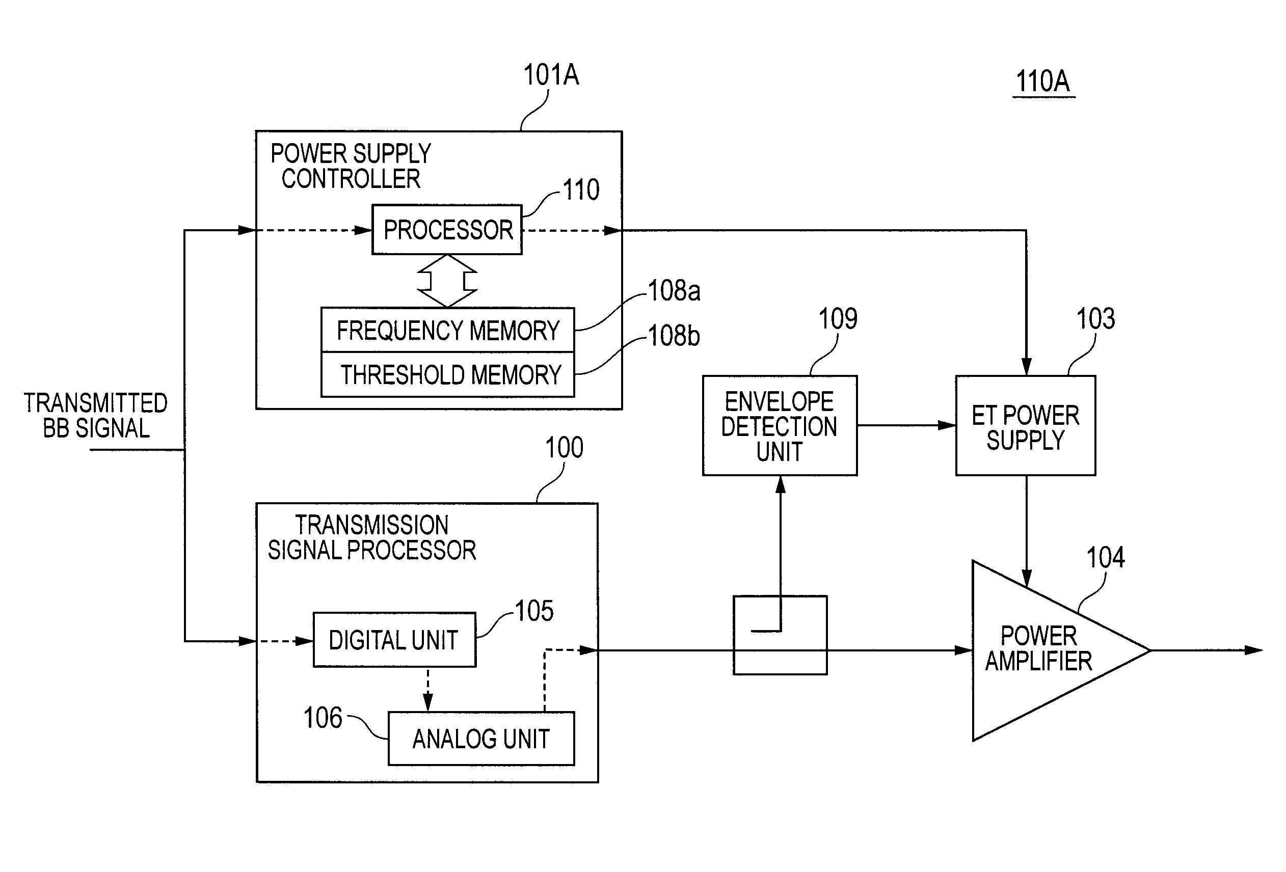
[0062]The configuration of the radio transmitter will be described with reference to FIG. 14. In FIG. 14, a radio transmitter 110A includes a transmission signal processor 100, a power amplifier 104, an ET power supply 103, an envelope detection unit 109, and a power supply controller 101A. The transmission signal processor 100 includes a digital unit 105 and an analog unit 106. The power controller 101A includes a processor 110 and a memory 108. Further, the memory 108 includes a frequency memory 108a and a threshold memory 108b.

[0063]The threshold memory 108b stores a plurality of thresholds which are ...


PUM


Abstract

The envelope tracking power supply includes a plurality of variable voltage supplies. A power supply controller of a power amplifier controls the plurality of variable voltage supplies so as to precisely divide the power supply voltage in a high frequency area, based on the voltage distribution of a received transmitted base band signal, in order to maximize the power added efficiency of the power amplifier. The power supply controller includes a threshold memory including a plurality of first zones, and a frequency memory including a plurality of second zones. The power supply controller changes the threshold held in the first zones so that each second zone approaches the average of the second zones.

Description

CLAIM OF PRIORITY[0001]The present application claims priority from Japanese patent application serial nos. 2011-125505 and 2012-050185, filed on Jun. 3, 2011, and Mar. 7, 2012, the contents of which are hereby incorporated by reference into this application.FIELD OF THE INVENTION[0002]The present invention relates to a radio transmitter and an envelope tracking power supply control method. More particularly, the present invention relates to a radio transmitter that improves the power added efficiency (PAE) by controlling a power supply, and to a method for controlling an envelope tracking power supply.BACKGROUND OF THE INVENTION[0003]In power amplifiers used in base stations in mobile or wireless communications, the improvement in the power added efficiency (PAE) is required in order to reduce operational costs. One of the PAE improvement technologies that have recently attracted attention is envelope tracking (hereinafter referred to as ET). In an RF power amplifier, PAE is define...

Claims


Application Information

Patent Timeline
Patent Type & Authority Patents(United States)
IPC IPC(8): H01Q11/12H04B1/04
CPCH04B1/0475H04B2001/0441H03F1/3223H03F3/24
Inventor NAMBU, HIROIOHNISHI, MASAMI
Owner HITACHI LTD
Why Eureka
Try Eureka