Three-group zoom lens

a three-group, zoom lens technology, applied in the field of three-group zoom lens, can solve the problems of increasing the total length not meeting the demands of miniaturization, and affecting the accuracy of the zoom lens, etc., and achieve the effect of higher resolution

Inactive Publication Date: 2005-03-17
FUJI PHOTO OPTICAL CO LTD
View PDF3 Cites 45 Cited by
  • Summary
  • Abstract
  • Description
  • Claims
  • Application Information

AI Technical Summary

Benefits of technology

The present invention relates to three-group zoom lenses for imaging devices, such as digital cameras and video cameras that use an image pickup element such as a CCD or CMOS, and achieves minaturization and higher resolution with a zoom ratio greater than three.

Problems solved by technology

Although it can satisfy the demands of miniaturization, zoom ratio, and resolution up to a zoom ratio of about three, when the zoom ratio exceeds three, the total length of the zoom lens increases so much that it does not satisfy the demands for miniaturization.
Additionally, in the three-group zoom lens described in Japanese Laid-Open Patent Application 2001-296476, because the third lens group moves monotonically toward the image side or moves in an arc that is convex toward the image side as discussed above, although it can satisfy the demands of miniaturization, high zoom ratio and higher resolution up to a zoom ratio of about three, when the zoom ratio exceeds three, correction of curvature of field at intermediate focal lengths becomes difficult.

Method used


Image

  • Three-group zoom lens
  • Three-group zoom lens
  • Three-group zoom lens

Examples


embodiments 1 and 2

of the present invention will now be individually described with further reference to the drawings.

embodiment 1

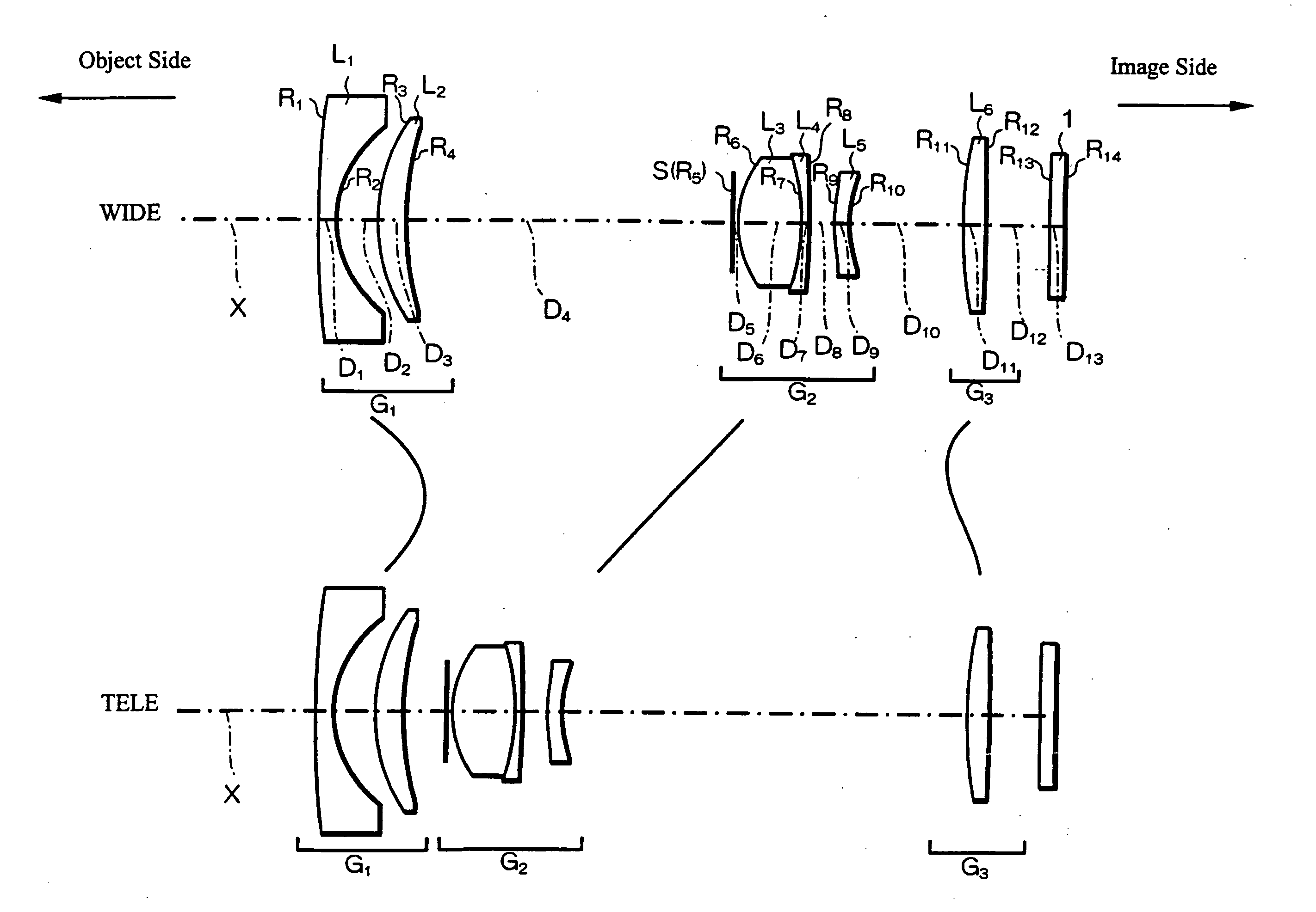
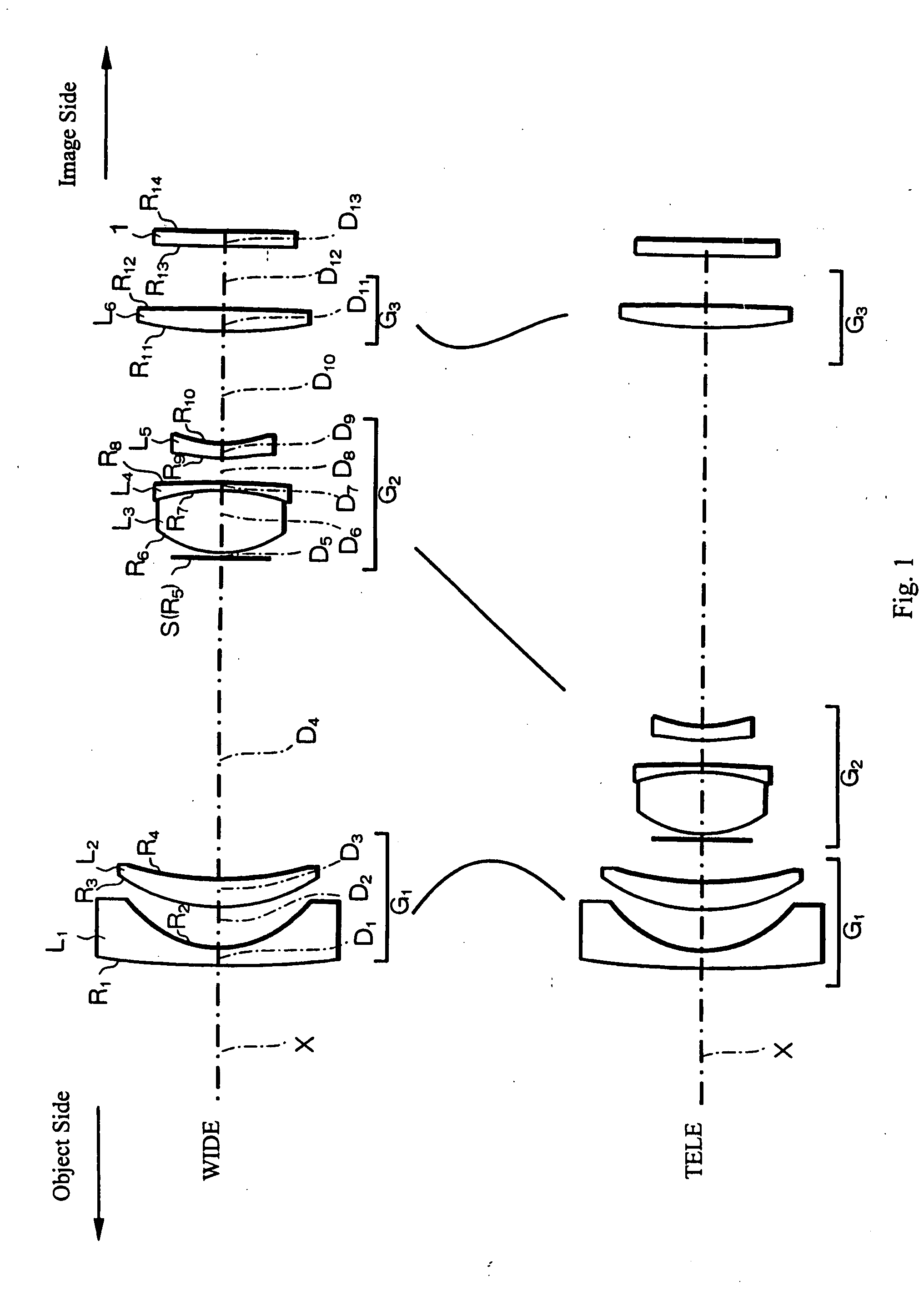
In Embodiment 1, as shown in FIG. 1, the first lens group G1 is formed of, in order from the object side, a first lens element L1 of negative refractive power and a meniscus shape with its image-side surface being concave and having a greater curvature than its object-side surface, and a second lens element L2 of positive refractive power and a meniscus shape with its object-side surface being convex and having a greater curvature than its image-side surface.

The second lens group G2 is formed of, in order from the object side, a stop S, a third lens element L3 that is biconvex, a fourth lens element L4 of negative refractive power and having a meniscus shape with its object-side surface being concave and having a greater curvature than its image-side surface, and a fifth lens element L5 of negative refractive power and having a meniscus shape with its convex surface on the object side. The lens element L3 and the lens element L4 are joined together to form a lens component.

The ...

embodiment 2

Embodiment 2 is very similar to Embodiment 1 and therefore only the differences between Embodiment 2 and Embodiment 1 will be explained. Embodiment 2 differs from Embodiment 1 in that in Embodiment 2, the first lens element L1 has a biconcave shape near the optical axis. Also, Embodiment 2 differs from Embodiment 1 in its lens element configuration by having different radii of curvature of the lens surfaces and different aspheric coefficients of the aspheric lens surfaces, as well as by having some different optical element surface spacings and by using some different refractive materials.

Table 5 below lists numerical values of lens data for Embodiment 2. Table 5 lists the surface number #, in order from the object side, the radius of curvature R (in mm) of each surface on the optical axis, the on-axis surface spacing D (in mm) between surfaces, as well as the refractive index Nd and the Abbe number νd (at the d-line of 587.6 nm) of each optical element for Embodiment 2. Listed i...


PUM


Abstract

A three-group zoom lens includes, in order from the object side, first, second and third lens groups having negative, positive and positive refractive power, respectively. During zooming from the wide-angle end to the telephoto end, the second lens group moves monotonically toward the object side while moving closer to the first lens group and farther from the third lens group, and the first and third lens groups reverse directions to define curved paths. The third lens group is closer to the object side at the wide-angle end and moves toward the object side for close focusing. The focal lengths of the zoom lens and its lens groups, the zoom ratio, the length of the zoom lens, and the half-field angle at the wide-angle end satisfy certain conditions in order to achieve a zoom ratio of at least three with favorable correction of aberrations.

Description

BACKGROUND OF THE INVENTION In digital cameras that have been rapidly becoming popular in recent years, three-group lenses are used for achieving miniaturization and improving aberration correction. Frequently used are rear-focus type three-group zoom lenses that provide closer focusing by moving the third lens group from the object side toward the image side. Japanese Laid-Open Patent Application H10-133115, Japanese Laid-Open Patent Application 2001-296476, and Japanese Laid-Open Patent Application 2003-035868 are exemplary publications that disclose such three-group zoom lenses. The three-group zoom lens described in Japanese Laid-Open Patent Application H10-133115 includes, in order from the object side, a first lens group having negative refractive power, a second lens group having positive refractive power and an aperture stop, and a third lens group having positive refractive power. During zooming from the wide-angle end toward the telephoto end, the first lens group moves ...

Claims


Application Information

Patent Timeline
Patent Type & Authority Applications(United States)
IPC IPC(8): G02B15/20G02B13/18G02B15/177
CPCG02B15/177G02B15/143507
Inventor ORI, TETSUYA
Owner FUJI PHOTO OPTICAL CO LTD
Why Eureka
Try Eureka