Separator grease retention and feed system for wheel spindle bearings

a technology of grease retention and feed system, which is applied in the direction of bearings, mechanical equipment, transportation and packaging, etc., can solve the problems of difficulty in properly lubricating and/or greasing the rolling elements of the bearing assembly, preventing proper positioning, and difficulty in lubrication, so as to reduce and eliminate drawbacks, eliminate the need for volume greasing, and reduce friction

Inactive Publication Date: 2005-03-17
DELPHI TECH INC
View PDF9 Cites 5 Cited by
  • Summary
  • Abstract
  • Description
  • Claims
  • Application Information

AI Technical Summary

Benefits of technology

[0012] The present invention reduces and eliminates the drawbacks with current methods of lubricating rolling elements of bearings. The present invention does so by providing a separator for a bearing, which includes a frame for housing the rolling elements, such as balls, of the bearing. This frame includes a plurality of cavities for receiving the rolling elements and further includes a lubrication channel. This lubrication channel is in fluid communication with each of the cavities of the separator. Grease and / or another lubricant may be provided within the channel prior to assembling the separator in the bearing assembly. The lubricant flows through the channel and into each of the cavities in order to lubricate the rolling elements so that they may roll on the surfaces of the races of the bearing with minimal friction and wear. Following insertion of the rolling elements into the cavities of the separator, the lubrication channel is filled with a lubricant, such as grease, and the separator is introduced into a bearing including an outer race and an inner race. Once inserted into the housing of the bearing, the separator is disposed within the outer race and inner race with the plurality of rolling elements disposed between the outer race and inner race and in movable contact with the races.
[0013] The lubrication channel design permits the assembly of the rolling elements into the separator, as normal, outside of the bearing assembly. However, the separator subassembly can be transferred to a lubrication station outside of the bearing assembly for introduction of a lubricant into the channel prior to final assembly of the separator into the bearing. At the same time, prior to final assembly, one can simultaneously check for ball presence, evacuate air from the open cavity, and then fill the open cavity with grease or other lubricant. Each “pre-greased” bearing separator subassembly can then be installed into the bearing assembly. This design permits a maximum volume of evenly distributed grease to each rolling element while eliminating the need for volume greasing.
[0014] The present invention ensures continued and directed lubrication for the rolling elements of the bearing assembly, thus assuring proper lubrication for the design life of the bearing assembly. Additionally, the lower volume and placement of lubricant in the bearing assembly will reduce bearing manufacturing costs and reduce the probability of lubricant bleed problems as noted above in the Background of the Invention. The lubrication channel design also reduces axial space outside of the rolling elements in the bearing design. The present invention also provides the advantages of allowing for a pre-greased separator subassembly, which can then be provided by component suppliers.

Problems solved by technology

Various generations of bearing-style drive and nondrive wheel bearing assemblies that feature separators, for load carrying capabilities and minimum torque / drag performance, are typically faced with difficult methods of properly lubricating and / or greasing the rolling elements of the bearing assembly.
This difficulty generally arises because the lubrication of the bearing assembly occurs from outside the bearing assembly after the bearing has been assembled.
Additionally, other bearing components, such as speed sensor rings and / or inner ring components, can provide further physical obstacles which prevent proper positioning of the lubricant in the separator of the bearing.
Further, difficulty in lubrication may arise because many bearings may include more than one separator.
However, as described above, much of this lubricant may be blocked from reaching the separator by other components of the bearing.
A second problem with this method of lubrication is that the lubricant may not be evenly distributed radially, in addition to the axial lubrication problem noted above.
This can translate into the pushing of a concentrated section of grease, or other lubricant, away from the rolling elements as the rolling elements begin to turn, thus leading to the problems of friction and wear.
A third problem with this lubrication method is higher costs.
This excess use of lubricant leads to higher costs of manufacture.
Yet a fourth problem is that the oil bleed, or separation, from this higher volume of grease can build up and be forced out of the bearing assembly through the sealing systems and onto corner brake components.
This reduces the amount of lubricant in the bearing and can lead to increased problems with friction and wear.

Method used


Image

  • Separator grease retention and feed system for wheel spindle bearings
  • Separator grease retention and feed system for wheel spindle bearings
  • Separator grease retention and feed system for wheel spindle bearings

Examples


Embodiment Construction

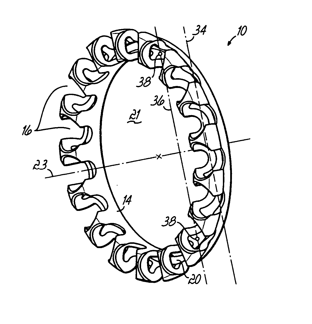
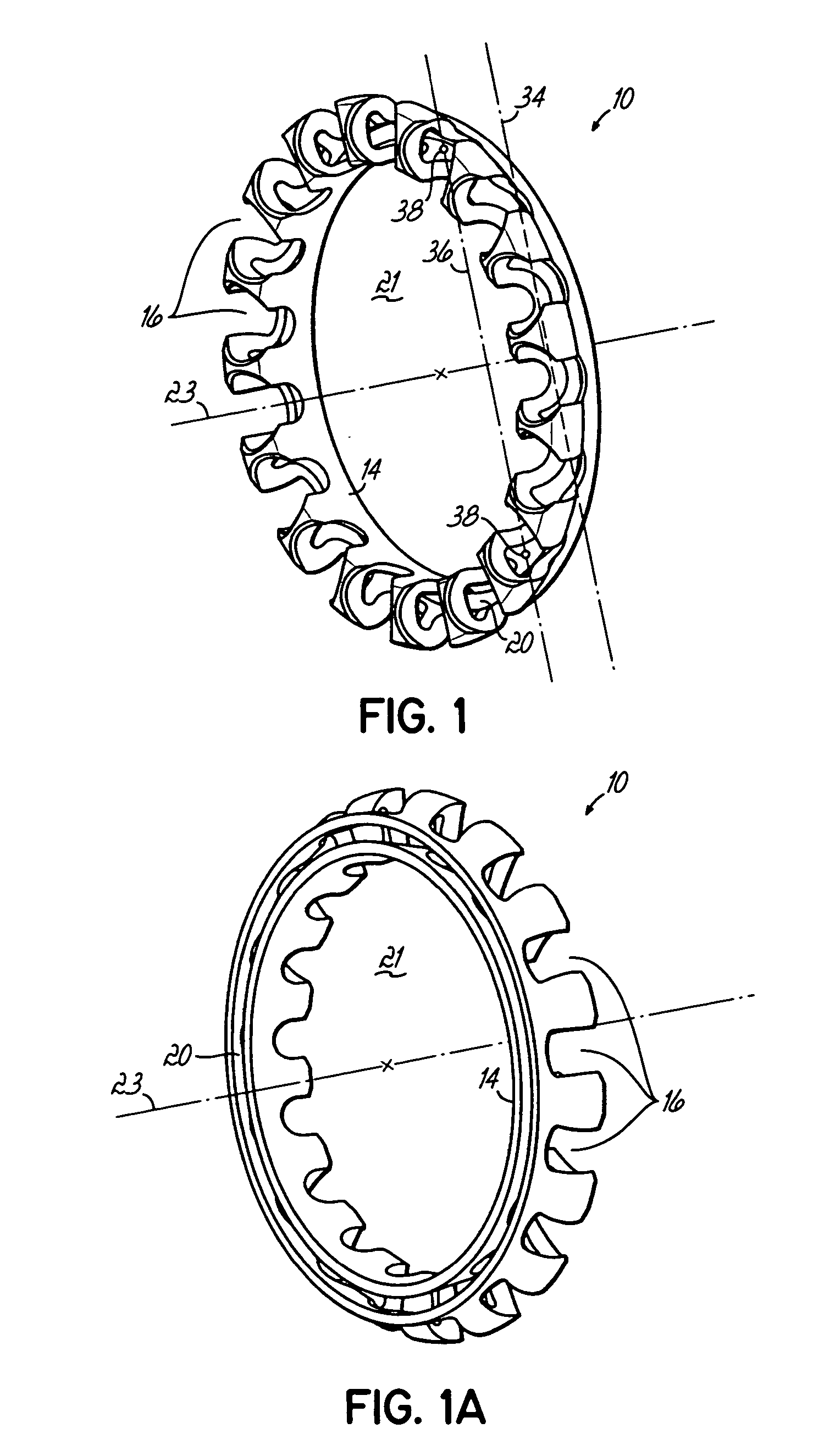
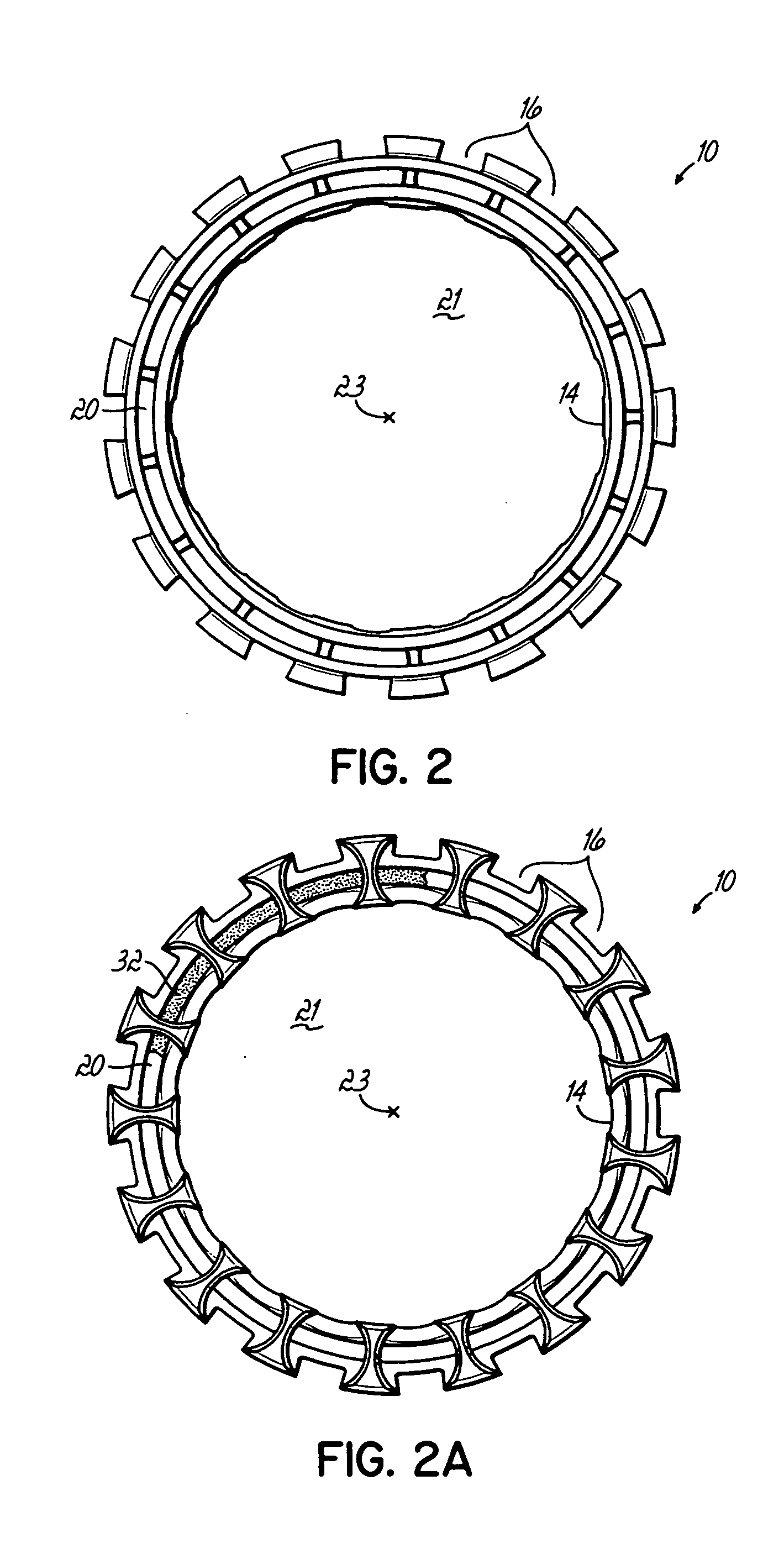
[0023] Referring to the Figures, one preferred embodiment of the present invention includes a separator 10 to be used as a component of a bearing 12. This separator 10 includes a frame 14 having a plurality of cavities 16 for receiving a plurality of rolling elements 18. This plurality of rolling elements 18 may, as shown in the illustrated embodiment, be ball members for use in a ball bearing. Thus, in the illustrated embodiment, each rolling element would be received by a cavity 16.

[0024] The frame 14 of the separator 10 may further include a lubrication channel 20. As can be seen with particular reference to FIGS. 1A, 2, and 2A, this lubrication channel 20 is in fluid communication with at least one of the plurality of cavities 16 disposed in the frame 14. In particular, in one embodiment, the lubrication channel 20 may be in fluid communication with each of the plurality of cavities 16. In the illustrated embodiment of the present invention, this communication between the lubri...


PUM


Abstract

A separator for a bearing comprising a frame including a plurality of cavities for receiving rolling elements and further including a lubrication channel in fluid communication with at least one of the plurality of cavities. This separator may be a component of a bearing including an inner race, an outer race, and a plurality of rolling elements disposed in each of the plurality of cavities of the separator and set to be in movable contact with the outer race and inner race of the bearing. A lubricant is introduced into the lubrication channel and flows into each of the plurality of cavities which provides evenly distributed lubrication to each rolling element of the bearing assembly.

Description

TECHNICAL FIELD [0001] The present invention relates to rolling-type bearings, and more particularly, to separators for rolling-type bearings. BACKGROUND OF THE INVENTION [0002] Bearings, such as rolling-type bearings, are used to support the wheels of vehicles, among other uses. Rolling-type bearings, such as ball bearings, are popular because rolling resistance is demonstrably much less than sliding resistance. These bearings, then, are characterized by rolling elements, such as balls or rollers, confined between outer and inner rings, referred to as races. The rolling elements are usually spaced uniformly by a cage, referred to as a separator. The rolling elements are important because they transmit loads from moving parts of a machine to stationary supports. [0003] When balls are used as rolling elements, they may be uniformly spherical. When rollers are used, they may be straight cylinders, or they may be barrel- or cone-shaped, or of other forms, depending upon the purpose of ...

Claims


Application Information

Patent Timeline
Patent Type & Authority Applications(United States)
IPC IPC(8): F16C19/18F16C33/41F16C33/66
CPCF16C19/186F16C33/414F16C33/6629F16C2326/02F16C33/6614
Inventor MEEKER, STEVEN E.SETTY, STEPHEN L.KROEGER, TODD M.
Owner DELPHI TECH INC
Why Eureka
Try Eureka