Deceleration-triggered automatic brake indication

a technology of automatic brakes and deceleration, which is applied in the direction of cycle equipment, program control, instruments, etc., can solve the problems of erroneous deceleration measurement, inability to obtain accurate deceleration measurement, and production of erroneous deceleration measurements, so as to improve the safety of slower moving electronic-mobility vehicles, reduce false positive indications, and improve deceleration detection and measurement

Active Publication Date: 2021-06-29
HAMMOCK JEFFEREY B
View PDF13 Cites 1 Cited by
  • Summary
  • Abstract
  • Description
  • Claims
  • Application Information

AI Technical Summary

Benefits of technology

[0019]The presently described invention fills needs in the art for solutions to problems associated with reliably detecting and indicating deceleration of vehicles and watercraft of various types, especially those that are moving over rough surfaces, moving with bipedal motion, and / or moving with relatively large changes in pitch and / or lateral accelerations. The invention, however, is applicable to passenger vehicles, trucks, tractors, and trailers as well. An accelerometer and / or a GPS system are used as deceleration detectors in an automatic deceleration indicating system and / or method that reduces or eliminates drawbacks and / or otherwise provides improvements over existing automatic deceleration indicating systems.
[0025]Advantages of the present invention arise, at least in part, from sensing that may involve the use of an accelerometer alone, a GPS-based deceleration indicating method and apparatus alone, or a combination of these to provide an apparatus, system and / or method providing redundancy with respect to deceleration measurement and / or detection. Data from an accelerometer used as a deceleration sensor is processed to compensate for vehicle orientation, transient g-forces from vehicle motion other than deceleration, and g-forces from rough terrain or water. An improved algorithm particularly suited to these types of vehicles is used to automatically indicate deceleration, for example by illuminating a brake light, that a vehicle is decelerating. This is particularly useful for improving the safety of slower moving electronic-mobility vehicles such as scooters, bicycles, and Segways® that use regenerative braking.
[0026]National Marine Electronics Association (NMEA) sentences are the output of a GPS Module. Time, position, and velocity data are included in the sentence and can be extracted but deceleration is not included in the NMEA sentence. As part of the present invention, data from a GPS receiver is processed to calculate deceleration which, advantageously, is independent of any forces of acceleration associated with vibrations, traversal of rough surfaces, gravity, and turns. For example, boats impact on waves that exert forces in different directions and cause very rapid changes in velocity but no sustained deceleration. Off road vehicles, including snowmobiles, traverse rough terrain that can cause them to pitch, roll, and / or yaw in various directions and complicate deceleration measurements based on accelerometer measurements in similar ways. Bicycle pedaling introduces roll from side to side and short duration forward accelerations and decelerations, which are difficult to filter out in g-force accelerometer based deceleration sensors. The use of a deceleration sensor processing GPS data, alone or in combination with an accelerometer overcomes certain limitations of purely accelerometer based methods and provides for improved deceleration detection and measurement and reduced false positive indication in particularly high motion dynamics environments.

Problems solved by technology

Consequently, any event in which wheel speed does not change with vehicle speed could result in an erroneous signal.
For example, when the wheels slide rather than rotate, it is impossible to obtain an accurate measurement of deceleration.
Abrupt changes in vertical acceleration are interpreted as a hazard events and cause brake light illumination even when the vehicle is not decelerating in the direction of motion.
Despite the above mentioned advances in deceleration indicating technologies, various drawbacks to these advances may be responsible for the small number products that have come into use in the transportation, sporting, and recreational industries.
For example, some systems do not warn of deceleration when a vehicle's electrical system fails or may interfere with normal brake signaling if the deceleration indicating circuitry fails.
A deceleration sensor requiring orientation-specific mounting can produce erroneous deceleration measurements when a vehicle is traveling on an incline or a decline because the direction of gravity changes with respect to set orientation of the sensor.
Vehicle motion on rough road surfaces, use of inadequate or sport-tuned suspension, traveling on incline / decline angle, and centrifugal forces experienced during turns are causes of false or erroneous illuminations in many existing deceleration indicating systems and methods.
The compensation for gravitational and other forces causing erroneous deceleration indication described is sufficient for most passenger vehicles and trucks on typical roadways, but may not be ideal for all vehicle types.
The greater pitch can complicate deceleration measurements by three axis accelerometer because of the contribution of gravity suddenly changes angle.

Method used


Image

  • Deceleration-triggered automatic brake indication
  • Deceleration-triggered automatic brake indication
  • Deceleration-triggered automatic brake indication

Examples


Embodiment Construction

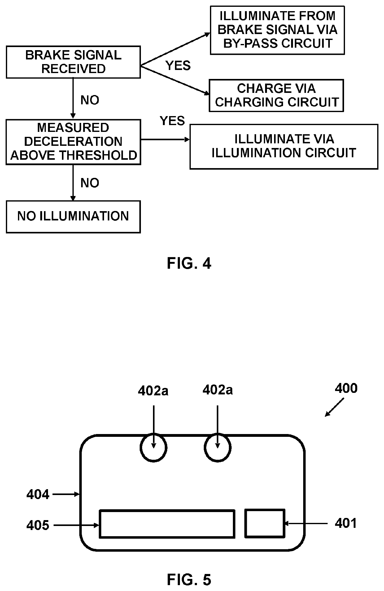
[0038]As used herein, a brake lamp may comprise any number of LEDs, incandescent, and / or other types of light bulbs. A brake lamp may comprise a combination of one or more tail lights with one or more brake lights. Brake lights may also be referred to as stop lamps. A brake lamp may also be a high mount or center high mount stop lamp, which may also be referred to as a third brake light. A brake lamp may be present in a powered vehicle such as an automobile, motorcycle, truck, snowmobile, or watercraft or a brake lamp may be present in a trailer designed to be pulled by and electrically connected to an electrical system of a motorized vehicle.

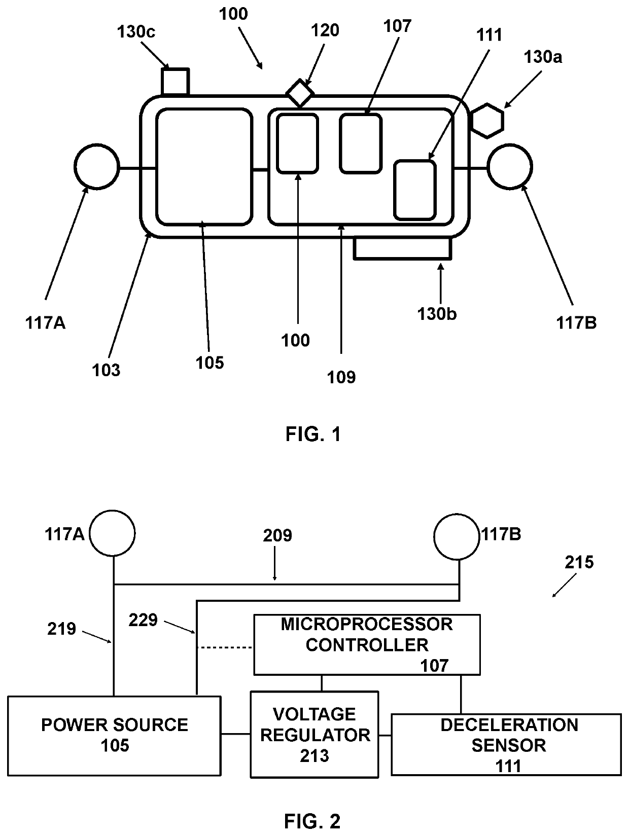
[0039]As used herein, a “portable sensor unit” is a sensor unit that designed to be reversibly and temporarily mounted to a vehicle in such a way that the acceleration forces experienced by the vehicle are also experienced by the sensor unit. A portable sensor unit does not require an electrical connection to a vehicle electrical system for pow...


PUM


Abstract

Automatic deceleration indication involves a deceleration sensor unit that senses deceleration and a microprocessor that causes deceleration warning light illumination when a sensed deceleration exceeds a threshold value. The deceleration sensor unit may include a solid state accelerometer acting as a deceleration sensor, a GPS module acting as a deceleration sensor, or both. The deceleration warning light my be a brake light, a separate warning light attached to a vehicle, or worn by an operator or passenger of bicycle, scooter, or motorcycle.

Description

RELATED APPLICATIONS[0001]This application claims priority under 35 U.S.C. 119(e) to provisional application 62 / 624,095 filed 30 Jan. 2018. This application is a Continuation-in-Part of, and claims priority under 35 U.S.C. 120 to, application U.S. Ser. No. 15 / 647,208 filed 11 Jul. 2017, which claims priority under 35 U.S.C. 119(e) to U.S. 62 / 360,867 and to U.S. provisional application 62 / 360,863, both filed 11 Jul. 2016.BACKGROUND OF THE INVENTIONField of the Invention[0002]The present invention relates generally to apparatus, methods, and systems for detecting and signaling sudden deceleration of a vehicle independent of any action by an operator of the vehicle or a brake system. More specifically, the invention relates to apparatus, methods, and systems that use Global Positioning System (GPS) data, alone or in combination with an accelerometer, to detect and indicate deceleration.Discussion of Related Art[0003]U.S. Pat. No. 6,225,896 describes an emergency deceleration warning ap...

Claims


Application Information

Patent Timeline
Patent Type & Authority Patents(United States)
IPC IPC(8): G06F7/70B60Q1/50G05B19/042B60Q1/00G01P15/18G01S19/52B62J6/01B62J6/04B60Q1/44
CPCB60Q1/50B60Q1/0094B62J6/01G01P15/18G01S19/52G05B19/042B60Q1/44B62J6/04G05B2219/25252B60Q2900/10B60Q1/2673B60Q1/2676G05B2219/2637B62J6/045B62J45/414B62J45/41G01S19/14G01S19/49
Inventor HAMMOCK, JEFFEREY B
Owner HAMMOCK JEFFEREY B
Why Eureka
Try Eureka