Marking labels for drive chains

a technology of drive chain and marking label, which is applied in the direction of identification means, paper/cardboard containers, instruments, etc., can solve the problems of high operating temperature, high rejection rate, and high operating temperature of drive chain, and achieve reliable marking, reduce rejection rate, and simplify the production process of closed drive chain

Inactive Publication Date: 2014-11-20
IWIS MOTORSYSTEME GMBH & CO KG
View PDF9 Cites 1 Cited by
  • Summary
  • Abstract
  • Description
  • Claims
  • Application Information

AI Technical Summary

Benefits of technology

[0008]It is therefore the object of the present invention to provide a drive chain for an internal combustion engine, which includes at least one chain link plate provided with a mark and which reduces or eliminates the drawbacks known in connection with conventional timing drive chains having marks thereon.
[0009]In the case of a generic drive chain, this object is achieved in that the mark is configured as a label, said label being affixed to the at least one chain link plate by means of an adhesive layer. The use of an affixed label as a mark allows a very simple identification, which is cost-efficient and does not affect the chain link plates, i.e. no hydrogen embrittlement of the chain link plates and no wear through copper chips when copper link plates are used. In addition, adhesive labels can be applied to the chain link plates at any moment in time of the production process of the drive chain, so that a separate supply of marked chain link plates to the assembly process of the drive chain can be avoided. This allows a reliable and direct identification of drive chains, and marking link plates, e.g. outer link plates made of copper, which have hitherto been installed such that no load is applied thereto are no longer necessary and are replaced by outer link plates subjected to load during the process. The use of a label allows not only marking of the drive chain as such, but it also allows detailed product data to be accommodated on the label. The labels can also be configured such that their surface is very small, so that also drive chains having very small dimensions can be identified. Conventional drive chains, which are normally configured with alternate inner chain links and outer chain links, are usually marked by means of the label on the outer link plate, so that no damage will be caused to the label through the drive chain itself.
[0010]According to a preferred embodiment, the label is made of a plastic material, preferably of polyester. Labels made of plastic exhibit a high resistance to oil and other aggressive ingredients of engine oil. Labels made of a plastic material are therefore well suited for use with drive chains for internal combustion engines. It will be expedient to choose preferably polyester as a plastic material. A label made of polyester is resistant to high temperatures and can easily be provided with detailed marks and information. According to a further embodiment, the plastic material of the label exhibits a temperature resistance of at least 130° C., preferably of at least 150° C. The marking labels applied to a chain link plate by means of an adhesive layer can thus also be used at high operating temperatures in an internal combustion engine, without the identification of the drive chain, e.g. the timing mark, being rendered undiscernible after only a short period of operation of the drive chain in an internal combustion engine.

Problems solved by technology

Drive chains for internal combustion engines are, during operation, exposed to very aggressive surroundings at high operating temperatures.
In addition to the drawback of higher storage costs, the systematic supply of marked chain link plates to the assembly process also leads to a complex production sequence entailing the risk of delays, and to an increase in downtimes and in the reject rate.

Method used


Image

  • Marking labels for drive chains
  • Marking labels for drive chains
  • Marking labels for drive chains

Examples


Embodiment Construction

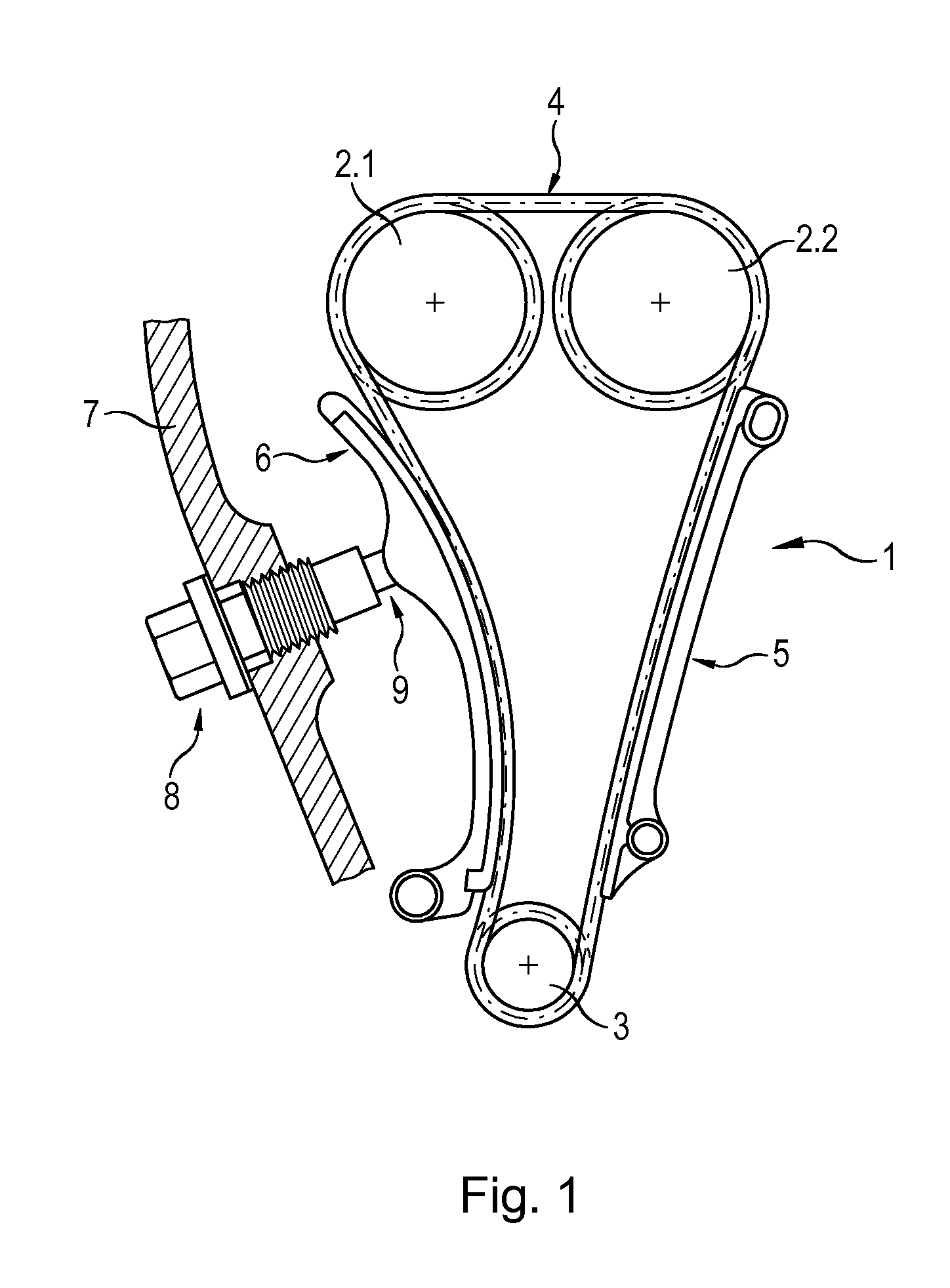
[0023]FIG. 1 shows a timing chain drive for an internal combustion engine. This timing chain drive 1 comprises two overhead camshaft chain wheels 2.1 and 2.2, a lower crankshaft chain wheel 3, a drive chain 4, i.e. a timing chain, wrapped around these chain wheels, a slide rail 5 and a pivotably arranged tensioning rail 6 pressed against the drive chain 4 by means of a chain tensioner 8 screwed in position in the crankcase 7. The chain tensioner 8 is normally connected to the engine oil hydraulic system so that its tensioning piston 9 is hydraulically pressed onto the pivotably arranged tensioning rail 6 thus keeping the drive chain 4 under tension. Both the slide rail 5 and the tensioning rail 6 abut with their sliding covers on the outer surface of the drive chain 4 running therealong.

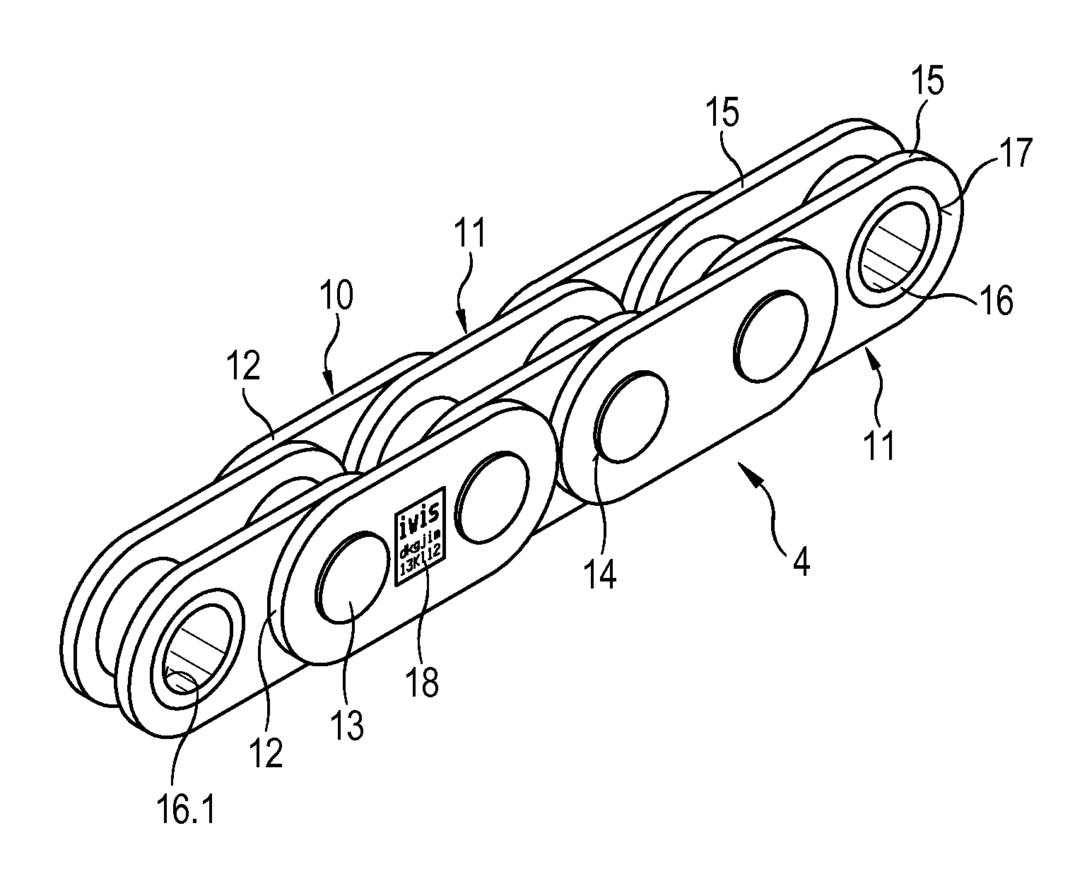
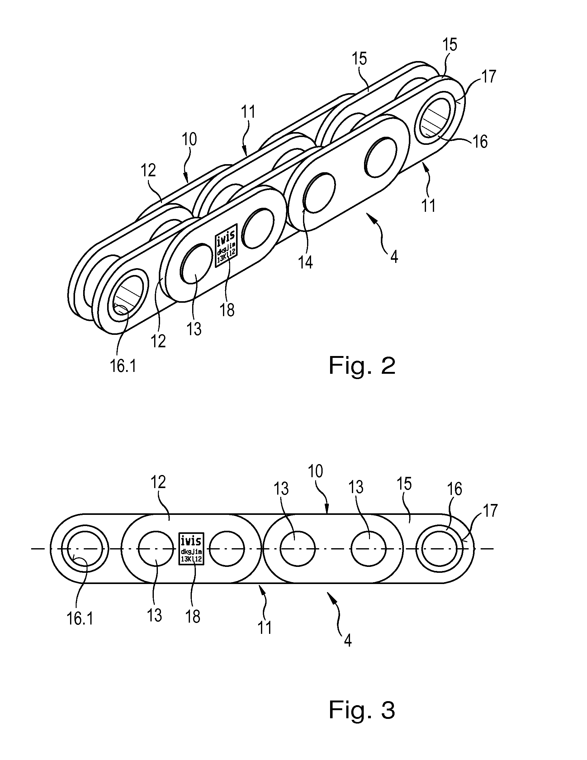
[0024]On the basis of FIGS. 2 and 3, a first embodiment of a drive chain 4 according to the present invention is shown in detail. The drive chain 4 comprises alternate outer chain links 10 and inner ...


PUM

PropertyMeasurementUnit
thicknessaaaaaaaaaa
thicknessaaaaaaaaaa
thicknessaaaaaaaaaa

Abstract

A drive chain for an internal combustion engine, e.g. a timing chain, comprises a plurality of chain links, which each include at least one chain link plate and which are interconnected via a chain hinge. At least one chain link plate is provided with a mark configured as a label and affixed to the chain link plate by means of an adhesive layer. In addition, a method is provided for marking a drive chain for an internal combustion engine, comprising a plurality of chain links, which each include at least one chain link plate and which are interconnected via a chain hinge, wherein a label is affixed to at least one chain link plate.

Description

CROSS-REFERENCE TO RELATED APPLICATION[0001]This application claims priority to foreign German patent application No. DE 102013008481.4, filed on May 16, 2013, the disclosure of which is incorporated by reference in its entirety.FIELD OF THE INVENTION[0002]The present invention relates to a drive chain for an internal combustion engine, in particular a timing chain, comprising a plurality of chain links, which each include at least one chain link plate and which are interconnected via a chain hinge, at least one chain link plate being provided with a mark. In addition, the invention relates to a method for marking such a drive chain comprising a plurality of chain links.BACKGROUND[0003]Drive chains are used in the automotive sector as timing chains for internal combustion engines and they are also used for driving auxiliary units. Timing chains connect the crankshaft chain wheel to at least one camshaft chain wheel of the engine in internal combustion engines and ensure that the cra...

Claims


Application Information

Patent Timeline
Patent Type & Authority Applications(United States)
IPC IPC(8): F01L1/02G09F3/10G09F3/00
CPCF01L1/022G09F3/0286G09F2003/0255G09F2003/023G09F3/10G09F11/12F16G13/02F16G13/06Y10T156/10
Inventor PALME, JENS
Owner IWIS MOTORSYSTEME GMBH & CO KG
Why Eureka
Try Eureka