Metallic cooling fin for a heat exchanger, especially for a motor vehicle

a technology of cooling fins and heat exchangers, which is applied in the direction of indirect heat exchangers, lighting and heating apparatus, transportation and packaging, etc., can solve the problems of increasing energy losses, reducing the output of heat exchangers, and causing greater energy losses, so as to reduce or eliminate drawbacks

Inactive Publication Date: 2003-05-01
BOUZIDA SAMY +2
View PDF0 Cites 9 Cited by
  • Summary
  • Abstract
  • Description
  • Claims
  • Application Information

AI Technical Summary

Benefits of technology

[0006] An object of the invention is to provide a metallic cooling fin which reduces or eliminates the drawbacks, such as those mentioned above, of known types of cooling fins.
[0008] The inclination in the lamellae of one group will thus be steeper as the order number assigned to the group is higher. Thus the lamellae in a first group will have a first inclination, the value of which is lower than that of a second group, which will itself be lower than that of any third group. To the extent that the fins have lamellae of at least two different inclinations, energy losses are considerably reduced.
[0009] Preferably, two adjacent lamellae, with different inclinations, constitute part of two groups of lamellae, the order numbers of which follow each other or precede each other. For example, a lamella of the first group will be followed by a lamella of the second group, the inclination of which is greater. Thus changes in direction of the fluid flow vary progressively, and therefore more gently, and this enables separation of the boundary layer to be limited, thus giving an increased working indirect heat transfer surface area.
[0010] According to a preferred feature of the invention, the lamellae which are located respectively in the first rank of a set of lamellae (that is to say at the start of the set) and or in the last rank of the same set (that is to say at the end of the set), form part of the group of lamellae of the lowest order number referred to as the first group. This makes the changes in direction of the fluid flow even more gentle.
[0013] In order to overcome this problem, and in accordance with another preferred feature of the invention, the cooling fin includes, upstream of the lamella of the first rank, a fixed upstream auxiliary lamella, the dimensions of which are substantially equal to or greater than the lamellae in the set, the said upstream auxiliary lamella being spaced away from the lamella of the first rank by an aperture of selected form. Thus, the free end of the upstream auxiliary lamella is located at a lower level than the respective levels of the lamellae in the set, and this leads to effective redirection of the fluid flow. The fluid is then at once well oriented, while, firstly, a good approach is obtained to the working edges of the lamellae in the series, and secondly, the probability of separation of the boundary layer from the wall is considerably reduced.
[0016] Where the cooling fin has at least two sets of lamellae in succession (comprising an upstream set and a downstream set), these latter may be connected together through the upstream auxiliary lamella of one set and the downstream auxiliary lamella of the other set. The junction between two sets of lamellae is a factor in energy loss, and this feature improves the output of the heat exchanger.

Problems solved by technology

Although it is true that the provision of this slatted-shutter configuration on the indirect heat transfer surfaces of the cooling fins improves heat transfer performance, it does at the same time increase energy losses, and this reduces the output of the heat exchanger.
In addition, it is well known in the art that the slats in the slatted-shutter configuration, where these consist of lamellae of constant inclination, lead to energy losses which are greater as the inclination is greater, as is generally the case in known heat exchangers, in which the fins typicall have an inclination of about 35.degree..
From the heat transfer point of view, such zones are detrimental because normal convection cannot take place in such zones.

Method used


Image

  • Metallic cooling fin for a heat exchanger, especially for a motor vehicle
  • Metallic cooling fin for a heat exchanger, especially for a motor vehicle
  • Metallic cooling fin for a heat exchanger, especially for a motor vehicle

Examples


Embodiment Construction

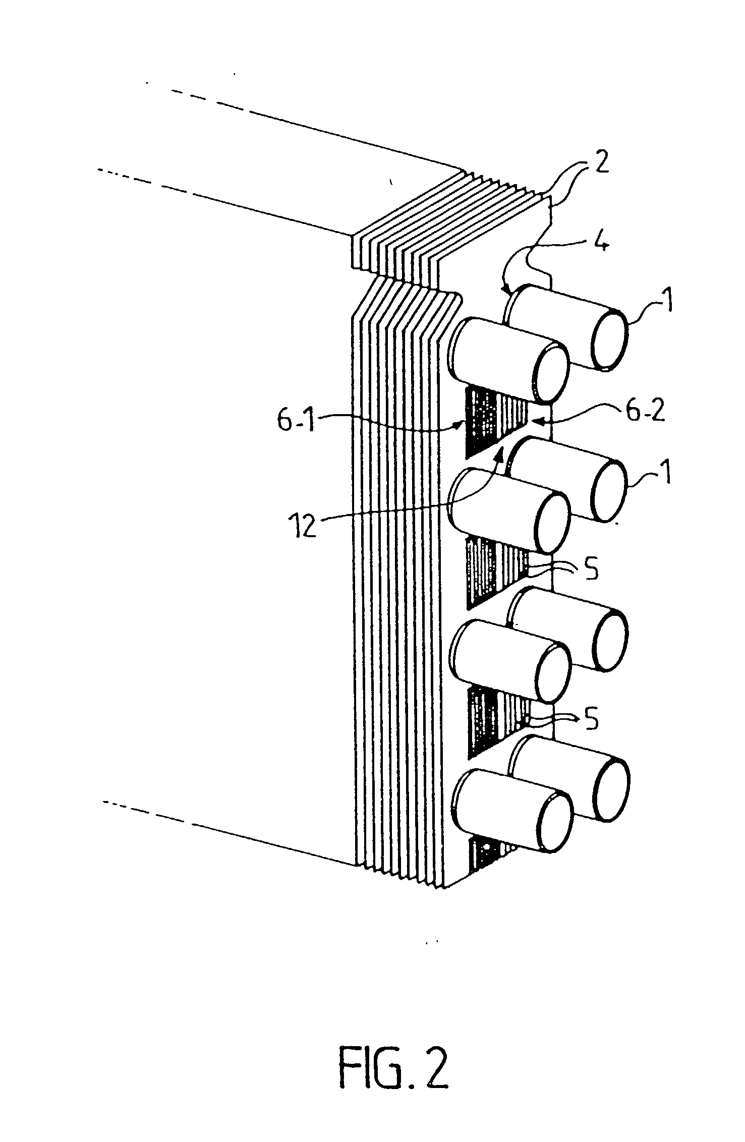
[0028] The main purpose of the heat exchanger is to transfer heat between a first fluid flowing within some of the elements of the heat exchanger, and a second fluid which flows on the outside of the same element. To this end, the heat exchanger generally consists of tubes having ends which are open into hollow headers, with the first fluid flowing in the tubes, this being for example a refrigerant fluid. The second fluid, which is typically air, flows around the outside of the tubes.

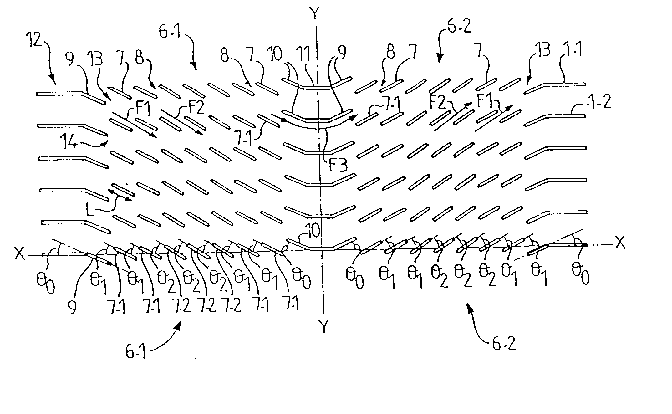
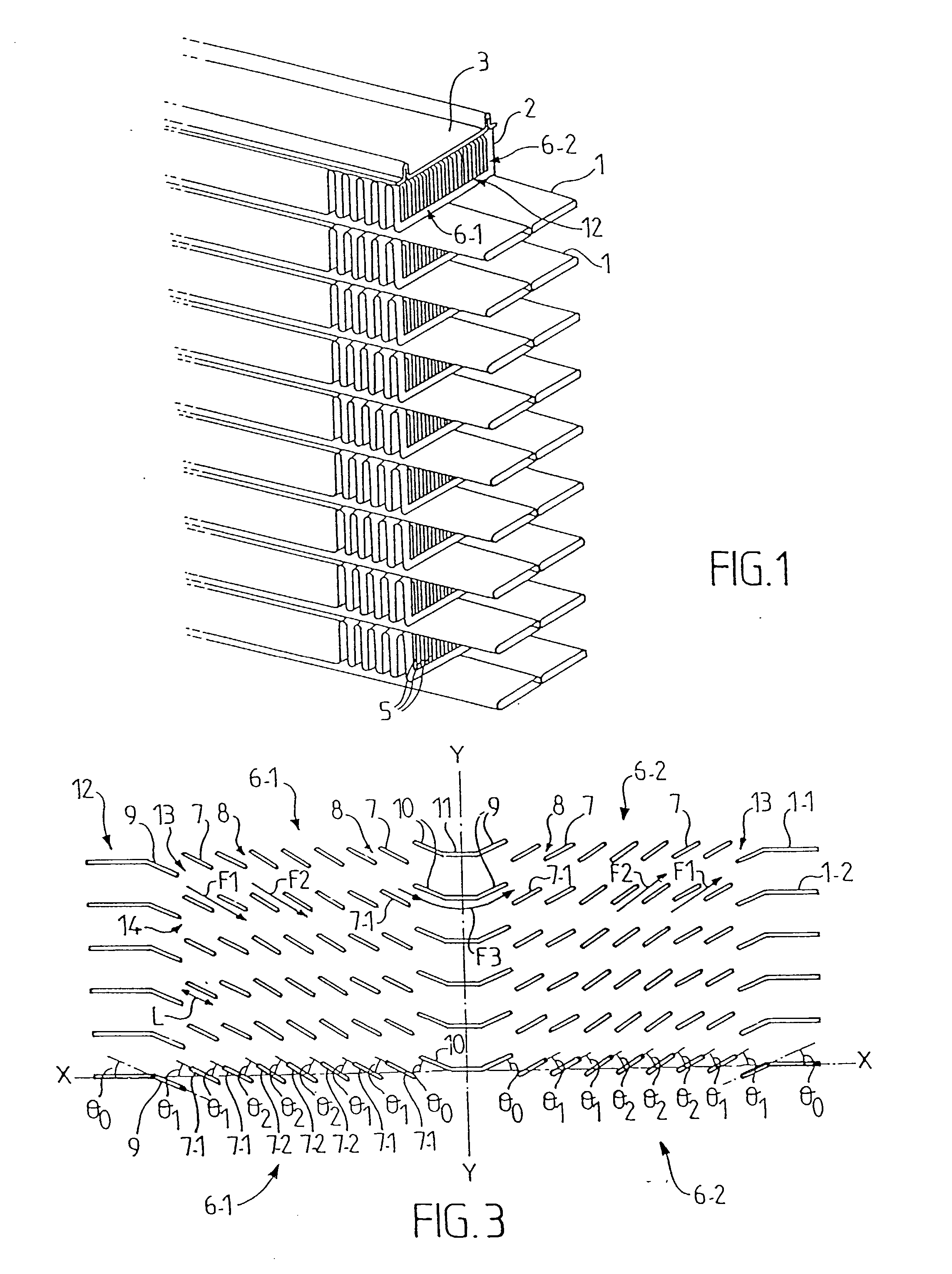
[0029] With a view to improving the heat exchange (or heat transfer) performance of the heat exchanger, it is usual to increase the heat exchange surface, which is that of the walls of the tubes, by juxtaposing to the tube walls indirect heat exchange surfaces, here in the form of fins 2. These fins are of metal, and are preferably made of aluminium or an aluminium alloy. They could however also be made in other metals, for example copper.

[0030] As shown in FIGS. 1 and 2, the fins will assume substantia...


PUM


Abstract

A metallic cooling fin for a motor vehicle heat exchanger has a central part having at least one set of fixed inclined lamellae, of selected form and spaced apart by apertures, the dimensions of which are predetermined to enable a fluid to pass between the lamellae. The lamellae in a common set are distributed in at least two groups, with the respective inclinations of the lamellae varying from one group to the other.

Description

[0001] This invention relates to heat exchangers, especially for motor vehicles. More particularly, the invention relates to metallic cooling fins used in heat exchangers of either the brazed type or the built-up type (in which the components are assembled together mechanically), the cooling fins defining indirect heat transfer surfaces which augment the heat transfer surfaces between the heat exchanger tubes (in which a first, hot or cold, fluid flows), and a second fluid, such as air, which flows around or between the tubes.[0002] Such cooling fins are generally made in the form of plates which are superimposed one above another in a stack in a heat exchanger of the built-up type, and in that case the tubes extend through the stack of plates. In head exchangers of the brazed type, the cooling fins are generally accordion-shaped, i.e. they are corrugated, and in that case they are interposed as spacers or inserts between the tubes.[0003] Some known types of cooling fins have a cent...

Claims


Application Information

Patent Timeline
Patent Type & Authority Applications(United States)
IPC IPC(8): F28F1/12B60H1/32F28F1/30F28F1/32
CPCF28F1/128F28F2215/04Y10S165/487F28F1/325
Inventor BOUZIDA, SAMYMIGNOT, CHRISTOPHEPOWERS, MIKE V.
Owner BOUZIDA SAMY
Why Eureka
Try Eureka