Deceleration-Triggered Automatic Brake Indication

Active Publication Date: 2020-04-23
HAMMOCK JEFFEREY B
View PDF0 Cites 1 Cited by
  • Summary
  • Abstract
  • Description
  • Claims
  • Application Information

AI Technical Summary

Benefits of technology

[0025]Advantages of the present invention arise, at least in part, from sensing that may involve the use of an accelerometer alone, a GPS-based deceleration indicating method and apparatus alone, or a combination of these to provide an apparatus, system and/or method providing redundancy with respect to deceleration measurement and/or detection. Data from an accelerometer used as a deceleration sensor is processed to compensate for vehicle orientation, transient g-forces from vehicle motion other than deceleration, and g-forces from rough terrain or water. An improved algorithm particularly suited to these types of vehicles is used to automatically indicate deceleration, for example by illuminating a brake light, that a vehicle is decelerating. This is particularly useful for improving the safety of slower moving electronic-mobility vehicles such as scooters, bicycles, and Segways® that use regenerative braking.
[0026]National Marine Electronics Association (NMEA) sentences are the output of a GPS Module. Time, position, and velocity data are included in the sentence and can be extracted but deceleration is not included in the NMEA

Problems solved by technology

Consequently, any event in which wheel speed does not change with vehicle speed could result in an erroneous signal.
For example, when the wheels slide rather than rotate, it is impossible to obtain an accurate measurement of deceleration.
Abrupt changes in vertical acceleration are interpreted as a hazard events and cause brake light illumination even when the vehicle is not decelerating in the direction of motion.
Despite the above mentioned advances in deceleration indicating technologies, various drawbacks to these advances may be responsible for the small number products that have come into use in the transportation, sporting, and recreational industries.
For example, some systems do not warn of deceleration when a vehicle's electrical system fails or may interfere with normal brake signaling if the deceleration indicating circuitry fails.
A deceleration sensor r

Method used


Image

  • Deceleration-Triggered Automatic Brake Indication
  • Deceleration-Triggered Automatic Brake Indication
  • Deceleration-Triggered Automatic Brake Indication

Examples


Embodiment Construction

:

[0038]As used herein, a brake lamp may comprise any number of LEDs, incandescent, and / or other types of light bulbs. A brake lamp may comprise a combination of one or more tail lights with one or more brake lights. Brake lights may also be referred to as stop lamps. A brake lamp may also be a high mount or center high mount stop lamp, which may also be referred to as a third brake light. A brake lamp may be present in a powered vehicle such as an automobile, motorcycle, truck, snowmobile, or watercraft or a brake lamp may be present in a trailer designed to be pulled by and electrically connected to an electrical system of a motorized vehicle.

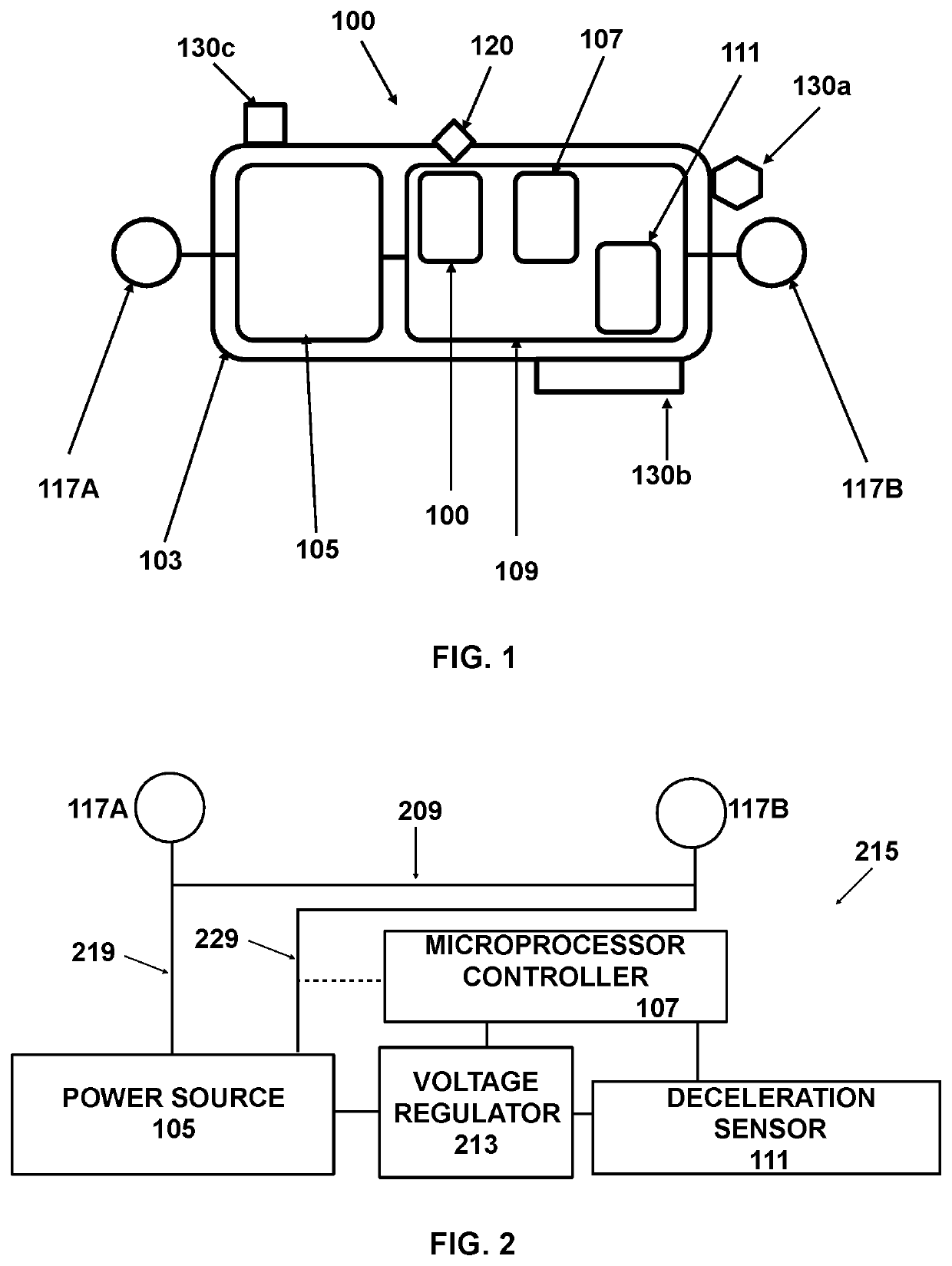
[0039]As used herein, a “portable sensor unit” is a sensor unit that designed to be reversibly and temporarily mounted to a vehicle in such a way that the acceleration forces experienced by the vehicle are also experienced by the sensor unit. A portable sensor unit does not require an electrical connection to a vehicle electrical system for po...


PUM


Abstract

Automatic deceleration indication involves a deceleration sensor unit that senses deceleration and a microprocessor that causes deceleration warning light illumination when a sensed deceleration exceeds a threshold value. The deceleration sensor unit may include a solid state accelerometer acting as a deceleration sensor, a GPS module acting as a deceleration sensor, or both. The deceleration warning light my be a brake light, a separate warning light attached to a vehicle, or worn by an operator or passenger of bicycle, scooter, or motorcycle.

Description

RELATED APPLICATIONS[0001]This application claims priority under 35 U.S.C. 119(e) to provisional application 62 / 624,095 filed 30 Jan. 2018. This application is a Continuation-in-Part of, and claims priority under 35 U.S.C. 120 to, application U.S. Ser. No. 15 / 647,208 filed 11 Jul. 2017, which claims priority under 35 U.S.C. 119(e) to U.S. 62 / 360,867 and to U.S. provisional application 62 / 360,863, both filed 11 Jul. 2016.BACKGROUND OF THE INVENTIONField of the Invention[0002]The present invention relates generally to apparatus, methods, and systems for detecting and signaling sudden deceleration of a vehicle independent of any action by an operator of the vehicle or a brake system. More specifically, the invention relates to apparatus, methods, and systems that use Global Positioning System (GPS) data, alone or in combination with an accelerometer, to detect and indicate deceleration.Discussion of Related Art[0003]U.S. Pat. No. 6,225,896 describes an emergency deceleration warning ap...

Claims


Application Information

Patent Timeline
IPC IPC(8): B60Q1/50G05B19/042B62J6/00B60Q1/00G01S19/52G01P15/18
CPCB60Q1/50B60Q1/44G05B19/042G01P15/18B62J6/01B62J6/04G01S19/52G05B2219/25252B60Q1/0094B60Q2900/10B60Q1/2673B60Q1/2676G05B2219/2637B62J6/045B62J45/414B62J45/41G01S19/14G01S19/49
Inventor HAMMOCK, JEFFEREY B.
Owner HAMMOCK JEFFEREY B
Why Eureka
Try Eureka