Debris collection systems, vehicles, and methods

a technology for collecting systems and debris, applied in the direction of cleaning filter means, suction cleaners, constructions, etc., can solve the problems of limiting the usefulness of the collection system and the vehicle, the inability of the device to effectively move large debris throughout the device, and the inability of the device to effectively move large debris

Inactive Publication Date: 2005-03-24
FEDERAL SIGNAL CORPORATION
View PDF33 Cites 31 Cited by
  • Summary
  • Abstract
  • Description
  • Claims
  • Application Information

AI Technical Summary

Problems solved by technology

While somewhat effective for debris collecting, such debris collection systems and vehicles suffer from various limitations that restrict their usefulness in the handling of collected debris.
For example, vacuum systems of such devices may cause such devices to be incapable of effectively moving large debris throughout the device (e.g., to the hopper and / or through the filter).
As such, the vehicles of the '530, '070, and '733 patents may be incapable of effectively handling larger and / or heavier debris, and the placement of the hopper in such devices is usually restricted to near the debris collection system.
An additional problem associated with the use of many known debris collection devices (particularly, street sweepers) is the need to spray liquid (typically water) during debris collection.
The use of water or other liquids can be undesirable, particularly in colder climates where water may freeze forming ice on the cleaned surface.
Although capable of substantially waterless debris collection, such debris collection vehicles are often inefficient in the handling of collected debris.
For example, the design of these sweepers requires inefficient use of the filter due to its placement in the hopper.
The use of a paddle-based vertical conveyor system and non-focused vacuum suction also can cause operational inefficiencies.

Method used


Image

  • Debris collection systems, vehicles, and methods
  • Debris collection systems, vehicles, and methods
  • Debris collection systems, vehicles, and methods

Examples


Embodiment Construction

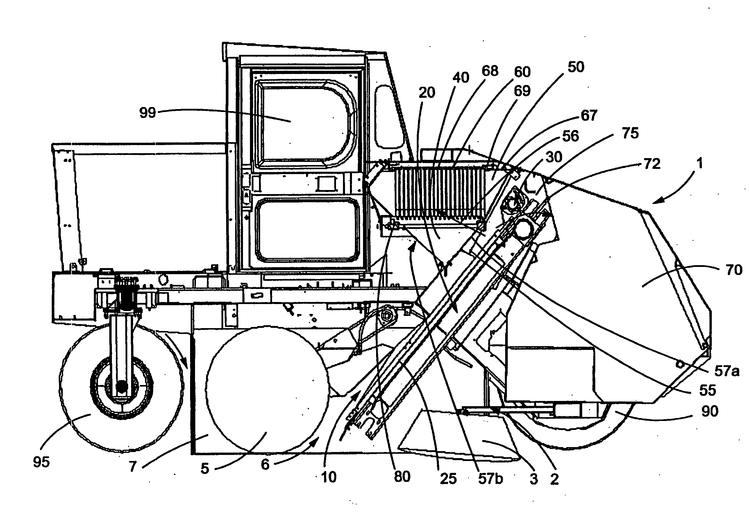
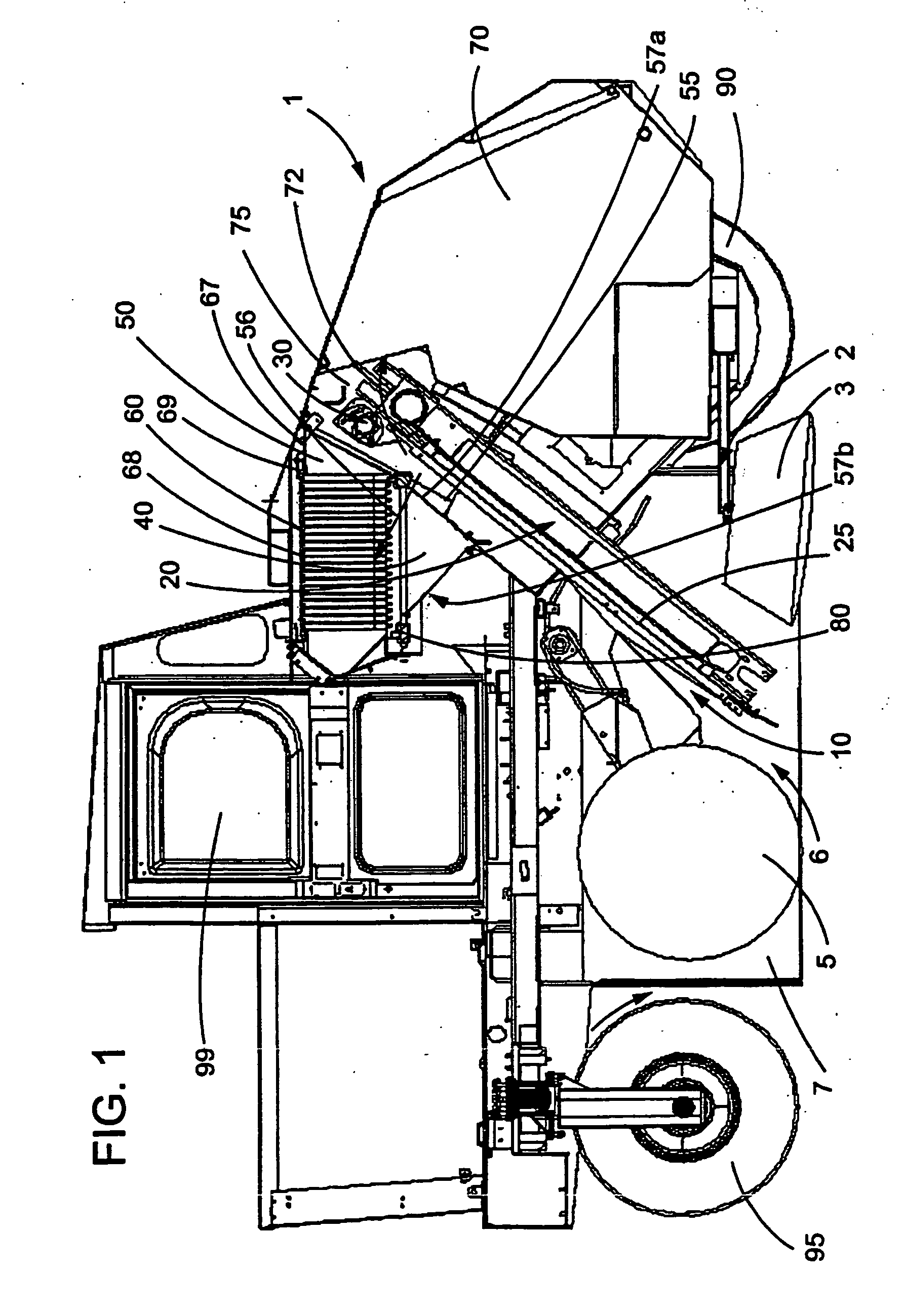
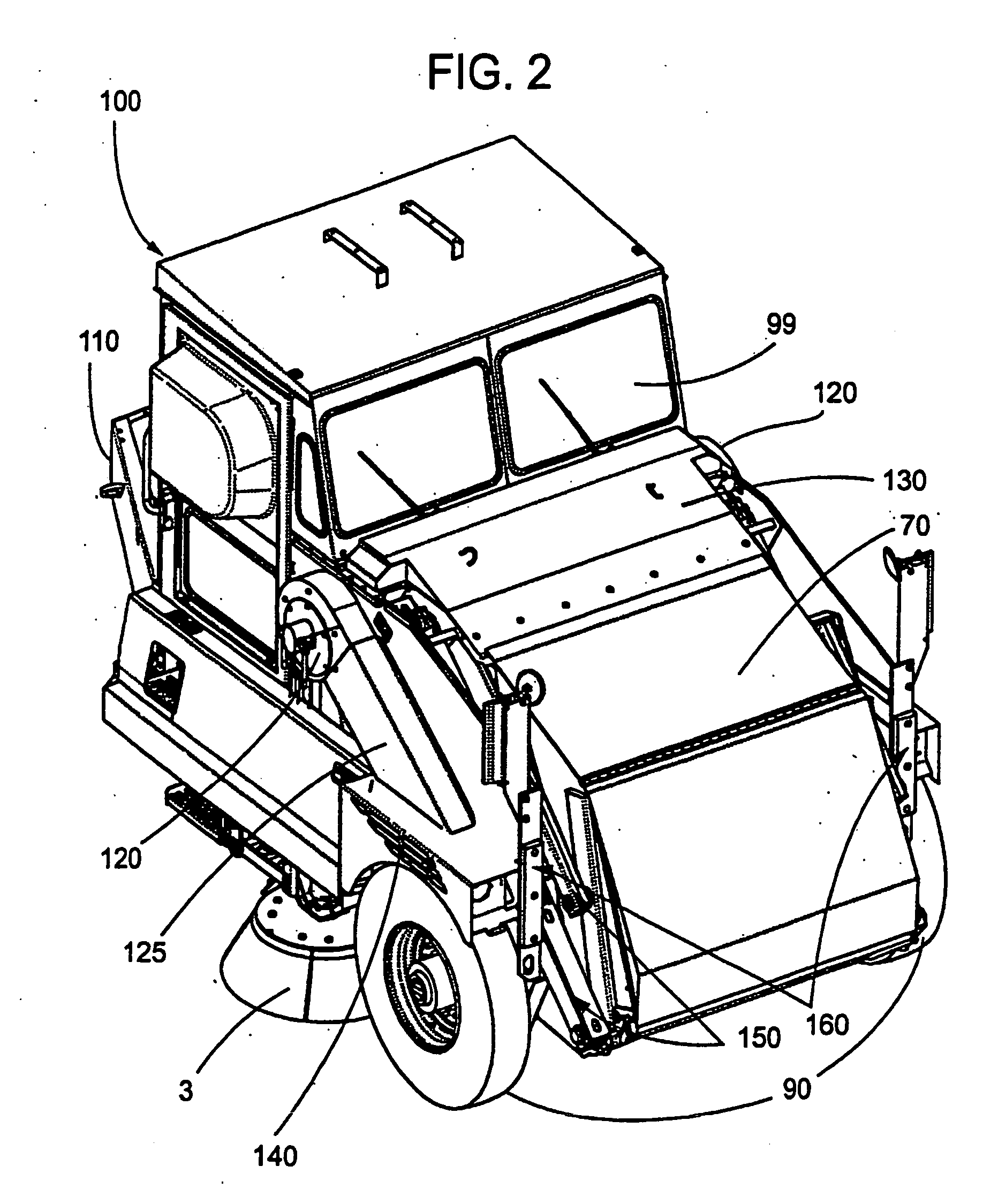
[0023] The invention provides alternative and improved systems for debris collection and handling (“debris processing”), vehicles comprising such systems, and related methods of collecting and handling debris. While several aspects of the invention are separately described herein, it will be understood that any aspect of any system, vehicle, device, or method described herein can be combined with any other aspect of the invention, unless otherwise stated or clearly contradicted by context.

[0024] In one aspect, among others, the invention provides a system for handling debris in a debris collection apparatus that includes a filter housing, a filter housing inlet, and a filter housing exhaust; a vacuum; a mechanical transport system; and a storage compartment. In operation, the mechanical transport system of the exemplary system delivers debris to the storage compartment, and the vacuum generates a directed suction force that, outside of the filter housing, is substantially limited t...


PUM


Abstract

The invention provides debris collection devices that include a debris contacting mechanism, a debris transport mechanism that is configured to receive debris moved by the debris contacting mechanism at an inlet and move such debris towards a debris storage compartment, and a filter and vacuum assembly. The filter and vacuum assembly includes an inlet disposed downstream of the inlet of the transport mechanism and upstream of the debris storage compartment, relative to the path of transported debris. In operation, the filter and vacuum assembly generate a primary air flow that draws the airborne particles into the inlet of the transport mechanism, along a path proximate to the transport mechanism, into the inlet of the filter and vacuum assembly and though a filter located within the filter and vacuum assembly without generating a substantial airflow through the storage compartment. Related debris collection and processing systems and methods also are provided.

Description

CROSS-REFERENCE TO RELATED PATENT APPLICATIONS [0001] This application is a continuation-in-part of U.S. patent application Ser. No. 10 / 074,777, filed Feb. 13, 2002, the entirety of which is hereby incorporated by reference.FIELD OF THE INVENTION [0002] This invention pertains to systems for collecting debris, vehicles comprising such systems (e.g., street sweepers), and related methods of handling debris. BACKGROUND OF THE INVENTION [0003] Motorized debris-collecting devices were first developed in the early 20th century. Since the first motorized street sweeper was put into use in 1914, there have been numerous modifications, improvements, and variations in the design of debris collection devices. U.S. Pat. Nos. 4,206,530, 4,615,070, and 5,943,733, for example, describe debris-collecting vehicles having several common features, including a brush debris collection system, a filter, a hopper for containing collected debris, and a vacuum for moving debris through the vehicles. While ...

Claims


Application Information

Patent Timeline
Patent Type & Authority Applications(United States)
IPC IPC(8): E01H1/05E01H1/08
CPCE01H1/053E01H1/0854E01H1/0845
Inventor STRAUSER, DANIEL P.
Owner FEDERAL SIGNAL CORPORATION
Why Eureka
Try Eureka