Bezel mounting assembly

Inactive Publication Date: 2005-03-24
HONG FU JIN PRECISION IND (SHENZHEN) CO LTD +1
View PDF4 Cites 9 Cited by
  • Summary
  • Abstract
  • Description
  • Claims
  • Application Information

AI Technical Summary

Benefits of technology

[0006] Accordingly, an object of the present invention is to provide a bezel

Problems solved by technology

However, this mounting assembly requires the bezel to have numerous barbs, which makes detachment of the bezel from the chassis inconvenient and laborious.
Additionally, the barbs are liable to break when too much force is applied thereon during the detachment process.
This mounting assembly requires

Method used


Image

  • Bezel mounting assembly
  • Bezel mounting assembly
  • Bezel mounting assembly

Examples


Example

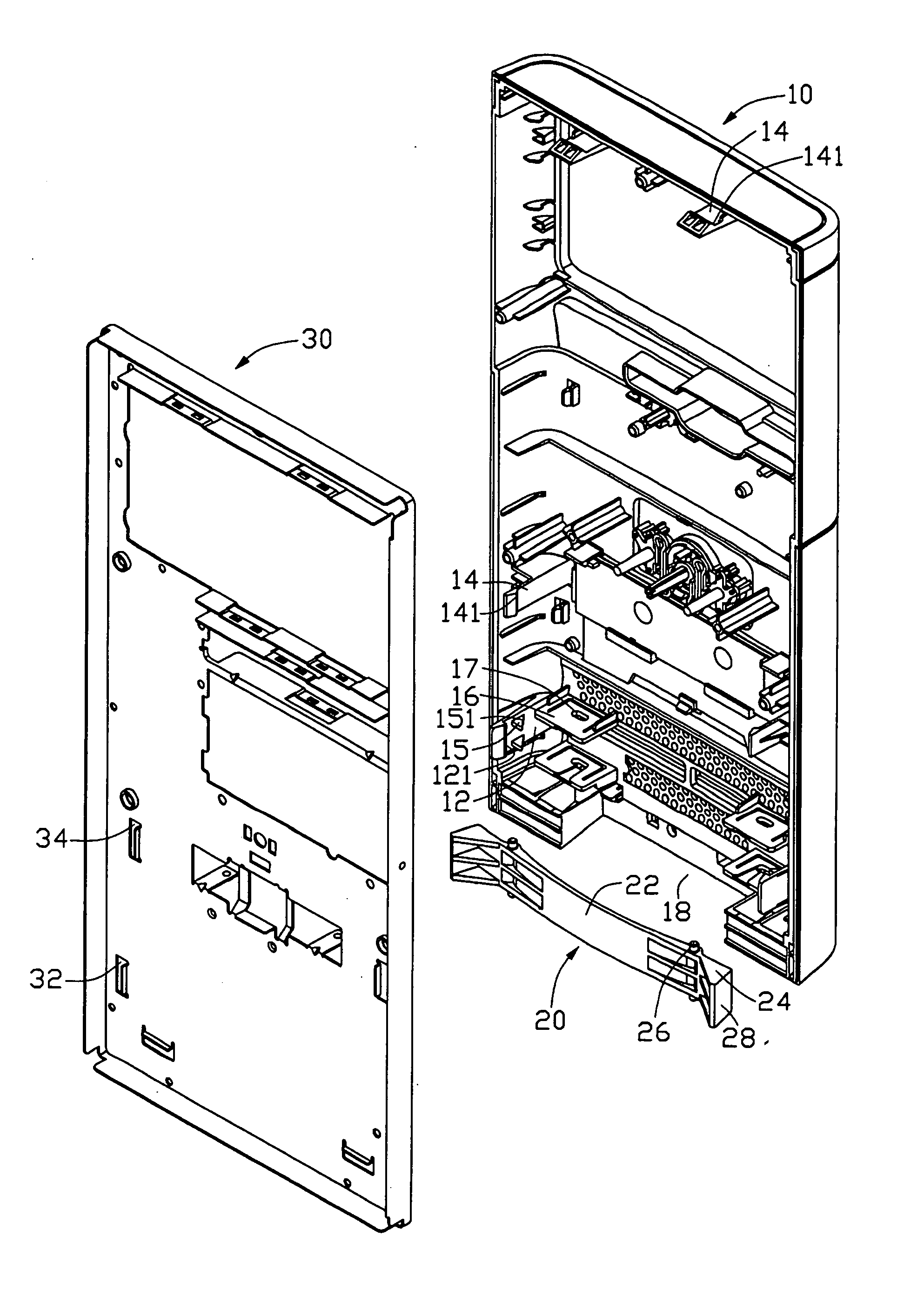
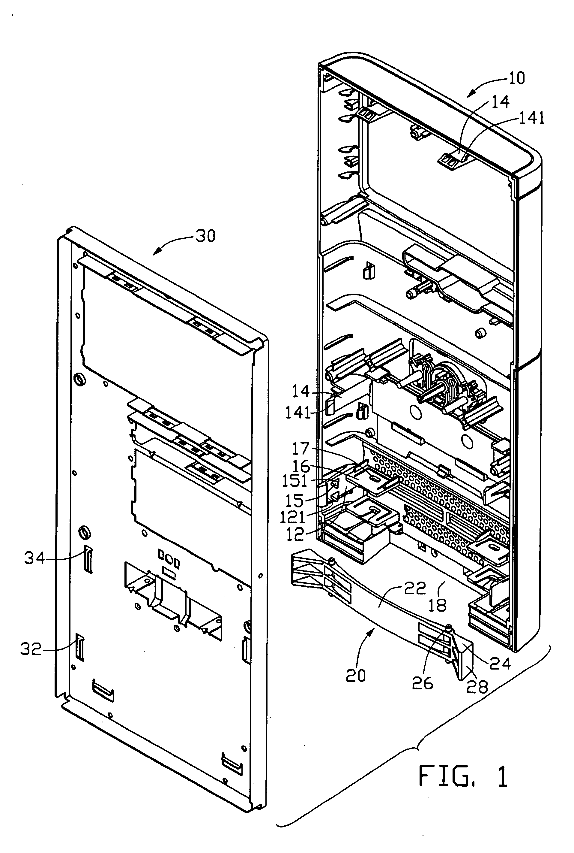
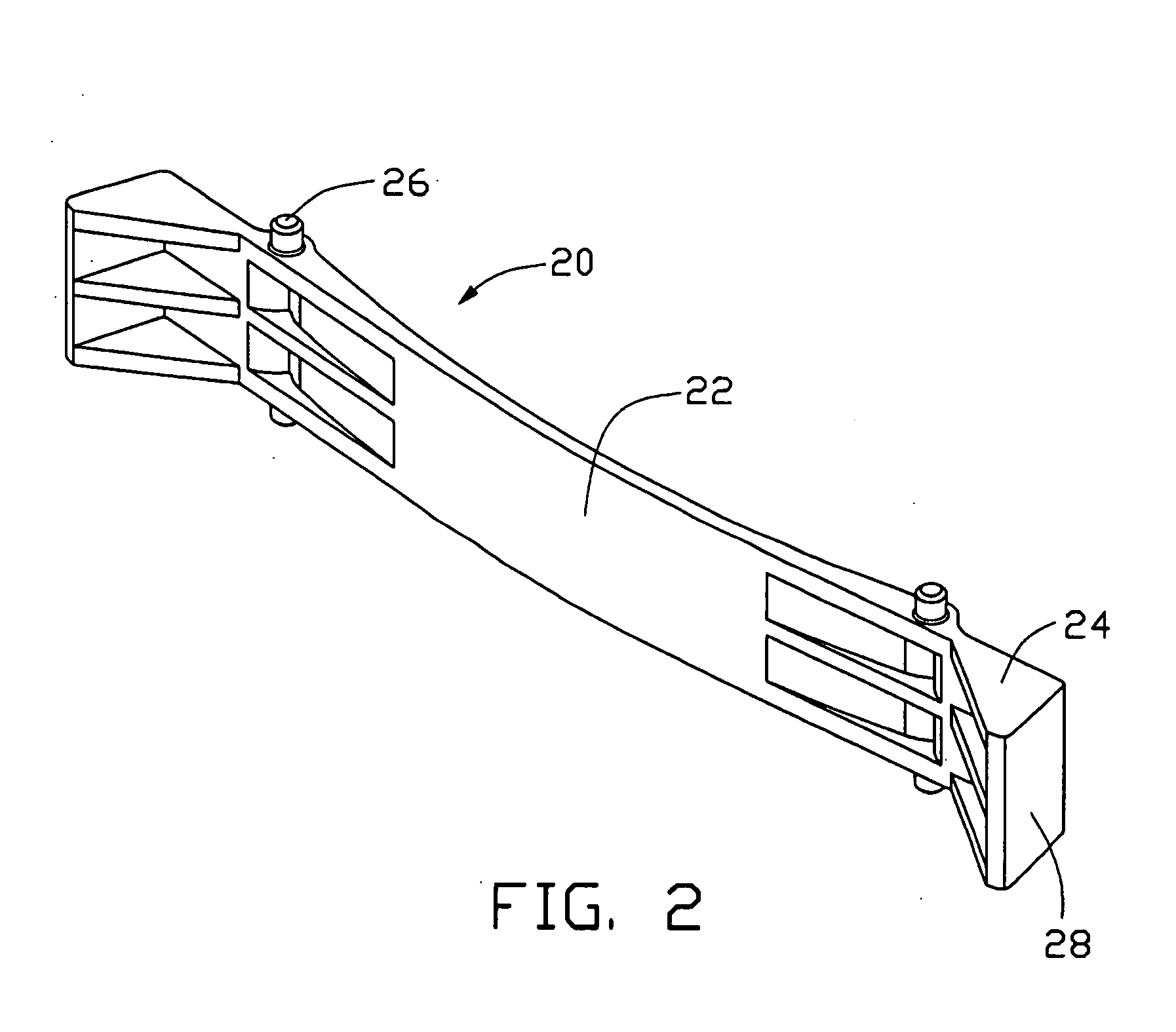
[0015] Referring to FIGS. 1 to 3, and 6, a bezel mounting assembly in accordance with a preferred embodiment of the present invention comprises a bezel 10, a front panel 30 of a computer enclosure 50, and a resilient member 20 assisting in detaching the bezel 10 from the front panel 30.

[0016] The bezel 10 is generally arch-shaped, the bezel 10 comprising a main portion (not labeled) and a pair of side portions (not labeled). A pair of spaced first hooks 12 is formed symmetrically on a bottom end of the bezel 10 at opposite side portions. The first hooks 12 each comprise a straight inner surface 121 at a forepart thereof. A pair of vertically spaced wedge-shaped touching blocks 15 is integrally formed besides the straight inner surface 121 on each first hook 12, each touching block 15 comprises an inclined side 151. A pair of vertically spaced retaining pieces 16 is formed on the main portion of the bezel 10 adjacent each first hook 12, each retaining piece 16 defines a sliding slot...


PUM


Abstract

A bezel mounting assembly of the present invention includes a bezel (10), a front panel (30) defining a pair of first slots (32) therein, and an arc-shape resilient member (20) attached to the bezel for detaching the bezel from the front panel. The bezel includes a pair of first hooks (12) corresponding to the first slots of the front panel. A pair of retaining pieces (16) is formed on the bezel and each defines a sliding slot (17) therein. A cutout (18) is defined in a bottommost portion of the bezel. The resilient member includes a pressing portion (22). A number of protrusions (26) are formed on the resilient member and are received in the corresponding sliding slots of the bezel. The pressing portion is pressed to drive the first hook outwardly; the first hooks are thereby disengaged from the first slots of the front panel.

Description

BACKGROUND OF THE INVENTION [0001] 1. Field of the Invention [0002] The present invention relates to a mounting assembly, and more particularly to a computer bezel mounting assembly with a simplified configuration and convenient usability. [0003] 2. Description of Prior Art [0004] A typical bezel is mounted to a computer case by means of a plurality of set screws or fasteners attached to the bezel and engaged in a plurality of fixing holes defined in the computer case. A typical bezel mounting assembly is disclosed in Taiwan Patent No. 115,733. The mounting assembly comprises a chassis and a bezel. Two sidewalls of the chassis each define a plurality of receiving slots in front portions thereof. Side edges of the bezel have a plurality of barbs engaging in corresponding slots of the chassis, thereby connecting the front bezel to the chassis. However, this mounting assembly requires the bezel to have numerous barbs, which makes detachment of the bezel from the chassis inconvenient an...

Claims


Application Information

Patent Timeline
IPC IPC(8): G06F1/18G11B33/12
CPCG11B33/127G06F1/181
Inventor CHEN, YUN LUNGSUN, DA LONG
Owner HONG FU JIN PRECISION IND (SHENZHEN) CO LTD
Why Eureka
Try Eureka