
Viewing device

a technology of a viewing device and a display screen, which is applied in the field of viewing devices, can solve the problems of cumbersome and large system sizes

Inactive Publication Date: 2005-03-24
ASH TECH RES
View PDF17 Cites 24 Cited by
  • Summary
  • Abstract
  • Description
  • Claims
  • Application Information

AI Technical Summary

Benefits of technology

[0012] In the capturing configuration, by spacing the capturing means above the base side, this creates the required distance between the capturing means and the surface to enable the desired visual image of the surface to be captured.
[0014] In one case the display element is substantially planar. The capture element may be substantially planar. Preferably in the stowed configuration, the plane of the capture element is substantially co-planar with the plane of the display element. The co-planar nature of the viewing device further enhances the compactness of the device. Ideally in the at least one capturing configuration, the plane of the capture element is substantially out-of-plane with respect to the plane of the display element.
[0015] In another embodiment the capture element is movable relative to the display element between the stowed configuration and a reading capturing configuration, and between the stowed configuration and a writing capturing configuration. Because the capturing means can be moved into both a reading configuration and a writing configuration, the viewing device enables a user to both read using the device and write using the device. The capturing means can be quickly and easily moved between the reading configuration and the writing configuration, thus the user can quickly and easily switch between the acts of reading and writing. In this manner, the viewing device of the invention provides a visually impaired person with the opportunity to switch between reading and writing in a natural manner. The capture element may be pivotably movable relative to the display element. Preferably the pivot axis is substantially parallel to the plane of the display element. Ideally the pivot axis is located closer to the display side than to the base side. By locating the pivot axis close to the display side, this ensures that the capturing means will pivot up, away from the base side to create the required distance between the capturing means and the surface to enable the desired visual image of the surface to be captured.

Problems solved by technology

However, such systems are generally large and cumbersome.

Method used


Image

  • Viewing device
  • Viewing device
  • Viewing device

Examples


Embodiment Construction

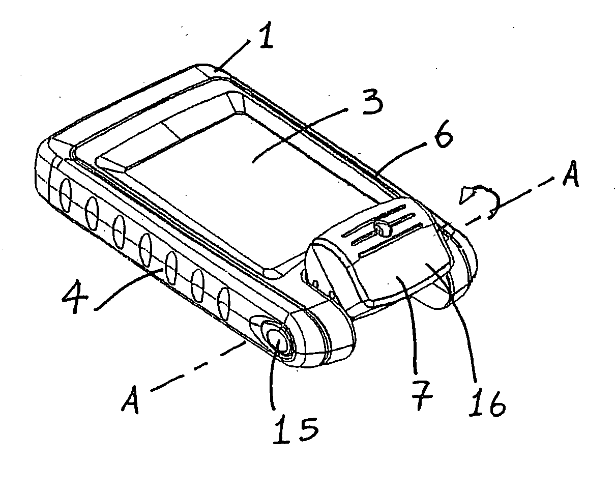
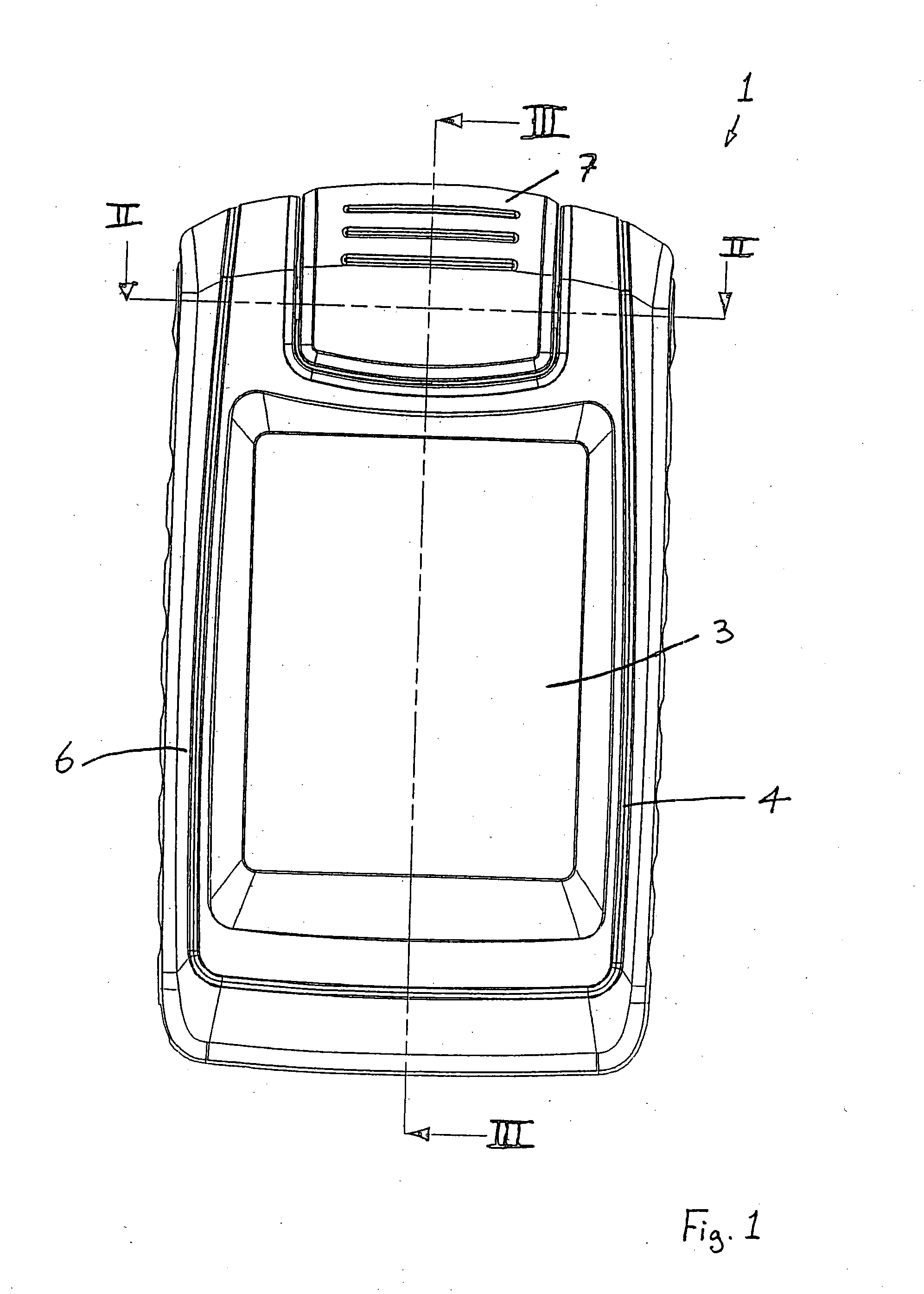
[0059] Referring to the drawings, and initially to FIGS. 1 to 10 thereof, there is illustrated a handheld, portable viewing device 1 according to the invention. The device 1 comprises means to capture a visual image of at least part of a surface, for example to capture the visual image of text on a page, and means to display a visual image. The visual image displayed may be the captured visual image, or alternatively the visual image displayed may be an image which is derived from the captured visual image.

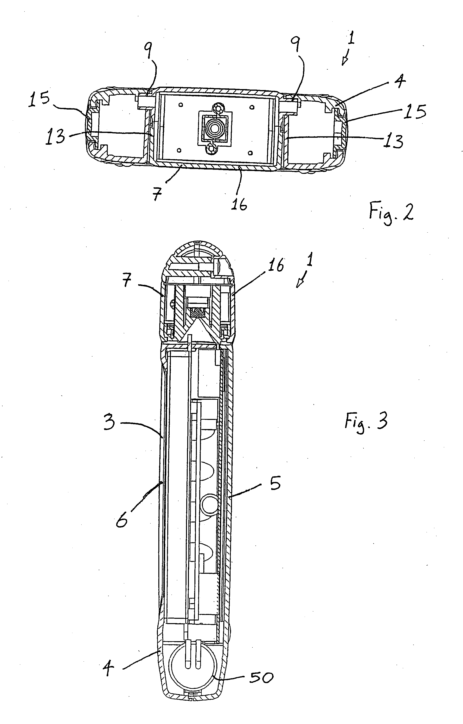
[0060] In this case, the capturing means is provided in the form of an electronic camera 2 housed in a camera part 7. The display means is provided in the form of an electronic monitor 3, such as a flat panel display monitor, housed in a monitor part 4.

[0061] As illustrated in FIG. 3, the monitor part 4 comprises a base side 5 suitable for placement, in use, against the surface of the page, and a display side 6 for displaying the captured visual image. The display side 6 is prov...


PUM


Abstract

A handheld viewing device (1) comprises an electronic camera (2) housed in a camera part (7) for capturing a visual image of text on a page, and an electronic monitor (3) housed in a monitor part (4) for displaying the visual image of the text. The camera part (7) is pivotably movable relative to the monitor part (4) from a stowed configuration to a reading configuration, and further to a writing configuration. In the stowed configuration, the plane of the camera part (7) is substantially co-planar with the plane of the monitor part (4), and thus the device (1) presents a very low-profile compact size and shape. In the reading configuration, the camera (2) points in the direction of the page, and the camera part (7) is spaced above the page to ensure that there is sufficient distance between the camera (2) and the page to enable the camera (2) to capture the visual image of the text. In the writing configuration, the camera (2) is still pointed in the direction of the page but slightly outwards to enable a user to place the tip of a pen within the view of the camera (2).

Description

[0001] The invention relates to a viewing device. In particular, this invention relates to a viewing device for use, for example, by a visually impaired person to assist in reading. [0002] It is known to employ a closed circuit television system to assist a visually impaired person while reading. Such systems typically include a camera positioned above a page of text to capture a visual image of the text, and a monitor to display the captured visual image. However, such systems are generally large and cumbersome. [0003] This invention is therefore aimed at overcoming at least some of the problems associated with the known systems. STATEMENTS OF INVENTION [0004] According to the invention there is provided a handheld viewing device comprising: [0005] a capture element for capturing a visual image of at least part of a surface; and [0006] a display element for displaying a visual image; [0007] the capture element being movable relative to the display element between a stowed configura...

Claims


Application Information

Patent Timeline
IPC IPC(8): G06K9/22H04N1/00H04N1/107H04N5/225H04N7/18
CPCH04N1/00347H04N5/2251H04N7/183H04N2201/0041H04N2201/0096H04N2201/0055H04N2201/0063H04N2201/0084H04N2201/0089H04N2201/0049H04N2201/0056H04N23/50H04N1/107H04N7/18G06V30/142
Inventor JOHNSTON, FRANCIS ALAN
Owner ASH TECH RES
Learn More