
Lighting unit with light source and optical waveguide

a technology of light source and optical waveguide, which is applied in the direction of lighting and heating apparatus, measurement apparatus components, vehicles, etc., can solve the problem of large space occupation in construction

Inactive Publication Date: 2005-03-24
SCHEFENACKER VISION SYST GERMANY
View PDF5 Cites 59 Cited by
  • Summary
  • Abstract
  • Description
  • Claims
  • Application Information

AI Technical Summary

Benefits of technology

[0006] Light rays emitted by the light source are directed through the optical waveguide. The light rays exit the optical waveguide at least through the light transmitting surface facing the reflector. They are reflected at the reflector and emitted into the environment. The area illuminated by the lighting unit, for example when the lighting unit is employed as a headlight, is large. At the same time, only a small space is required for the lighting unit as a result of the redirection of the light rays. Moreover, the light source can be mounted in an easily accessible location on the lighting unit.

Problems solved by technology

This construction requires a large amount of space.

Method used


Image

  • Lighting unit with light source and optical waveguide
  • Lighting unit with light source and optical waveguide
  • Lighting unit with light source and optical waveguide

Examples


Embodiment Construction

[0016] The following description of the preferred embodiment(s) is merely exemplary in nature and is in no way intended to limit the invention, its application, or uses.

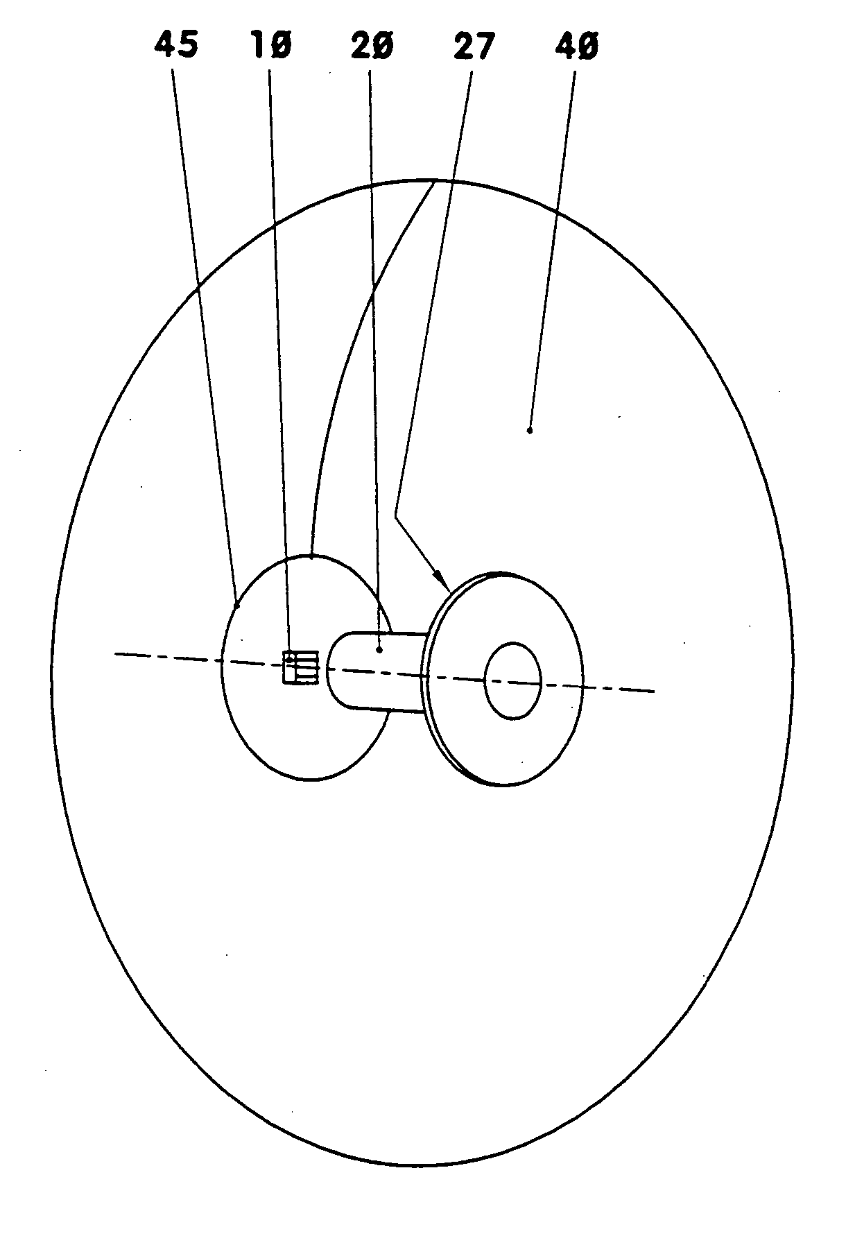
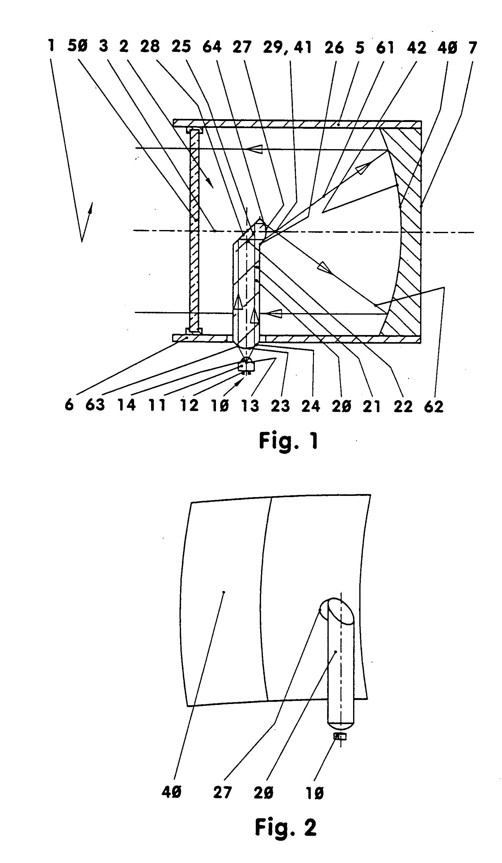
[0017]FIGS. 1 and 2 show a lighting unit, for example a headlight for a motor vehicle. The lighting unit includes a housing on which are arranged a light source, an optical waveguide, a reflector and a diffusion plate. The optical waveguide that follows the light source radiates the light emitted by the light source toward the reflector, and the reflector reflects the light through the diffusion plate into the environment.

[0018] The length of the lighting unit corresponds approximately to its height. Its width perpendicular to the plane of the drawing in FIG. 1 is approximately 80% of its length; compared with FIG. 2.

[0019] The light source is, for example, attached to the outside of the housing base, in a manner not shown in detail in FIG. 1. It is a light-emitting diode, for example. This consists of electronic ...


PUM


Abstract

The invention relates to a lighting unit with at least one light source and at least one optical waveguide following the light source, said waveguide having at least one light transmitting surface. To this end, the lighting unit has at least one reflector. In addition, at least one light transmitting surface of the optical waveguide faces the reflector. A lighting unit with an optical waveguide which has a large illuminated area and requires only a small space is provided.

Description

CROSS-REFERENCE TO RELATED APPLICATION [0001] This application claims priority to German Patent Application No. 103 36 162.6 filed on Aug. 7, 2003. FIELD OF THE INVENTION [0002] The invention relates to a lighting unit with at least one light source and at least one optical waveguide following the light source, said waveguide having at least one light transmitting surface. BACKGROUND OF THE INVENTION [0003] Such a lighting unit is known from DE 199 30 461 A1. To achieve a large illuminated area, this lighting unit includes a light source followed by two optical waveguides arranged in series. This construction requires a large amount of space. SUMMARY OF THE INVENTION [0004] The present invention is based on the object of developing a lighting unit with an optical waveguide which has a large illuminated area and requires only a small space. [0005] This object is attained with the features of the main claim. To this end, the lighting unit has at least one reflector. In addition, at le...

Claims


Application Information

Patent Timeline
Patent Type & Authority Applications(United States)
IPC IPC(8): F21S8/10F21S8/12G02B6/00F21V7/00F21V7/06F21V8/00F21W101/10F21W101/14F21W107/10F21Y101/02
CPCF21S48/1241F21S48/215F21Y2101/02F21V7/0008F21S48/2225F21Y2115/10F21S41/24F21S43/14F21S43/315F21S43/40F21S41/338F21S41/36F21S41/20F21W2102/00
Inventor ERBER, ANDREAS
Owner SCHEFENACKER VISION SYST GERMANY
Features
  • Generate Ideas
  • Intellectual Property
  • Life Sciences
  • Materials
  • Tech Scout
  • Unparalleled Data Quality
  • Higher Quality Content
  • 60% Fewer Hallucinations
Learn More