
Multi-biometric finger sensor including optical dispersion sensing pixels and associated methods

a biometric and finger sensor technology, applied in the field of biometric sensing, can solve the problems of two different sensors being relatively complicated, prior art multi-biometric systems may have significant drawbacks, and multi-biometric systems may be more difficult to spoof, etc., to achieve accurate, compact, reliable

Inactive Publication Date: 2005-03-24
APPLE INC
View PDF24 Cites 20 Cited by
  • Summary
  • Abstract
  • Description
  • Claims
  • Application Information

AI Technical Summary

Benefits of technology

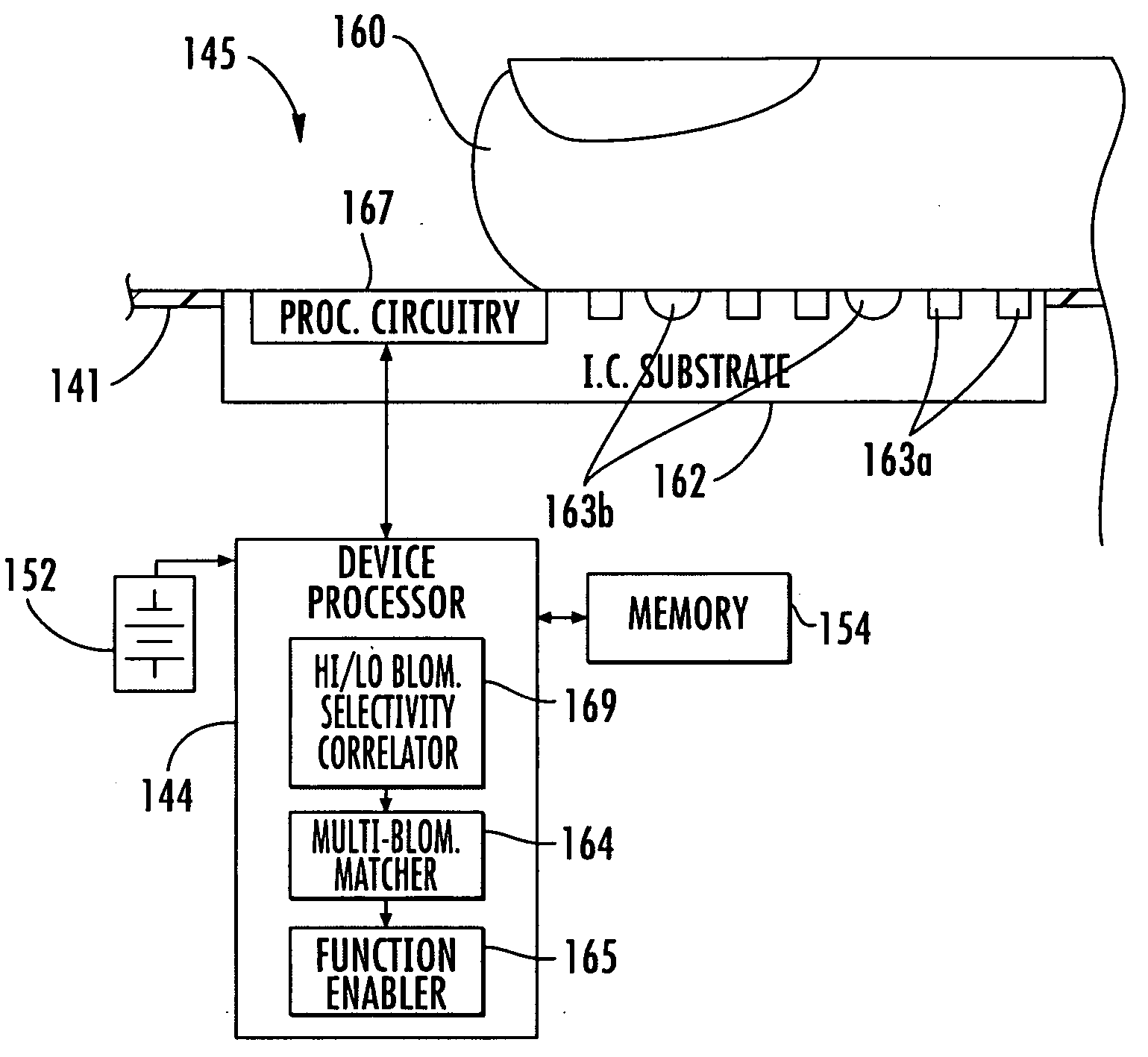
[0010] In view of the foregoing background, it is therefore an object of the present invention to provide an accurate, compact, and reliable finger multi-biometric sensor and associated methods.

Problems solved by technology

Such a multi-biometric system may be more difficult to spoof, because each of the biometrics needs to be spoofed to compromise the system as a whole.
Unfortunately, the prior art multi-biometric systems may have significant drawbacks.
Those having two different sensors are relatively complicated, and expensive to install and operate.
Those that require multiple presentations of a user's body part, for example, are inconvenient.
The requirement for multiple steps also slows the process.

Method used


Image

  • Multi-biometric finger sensor including optical dispersion sensing pixels and associated methods
  • Multi-biometric finger sensor including optical dispersion sensing pixels and associated methods
  • Multi-biometric finger sensor including optical dispersion sensing pixels and associated methods

Examples


Embodiment Construction

[0045] The present invention will now be described more fully hereinafter with reference to the accompanying drawings, in which preferred embodiments of the invention are shown. This invention may, however, be embodied in many different forms and should not be construed as limited to the embodiments set forth herein. Rather, these embodiments are provided so that this disclosure will be thorough and complete, and will fully convey the scope of the invention to those skilled in the art. Like numbers refer to like elements throughout, and prime notation is used to indicate similar elements in alternate embodiments.

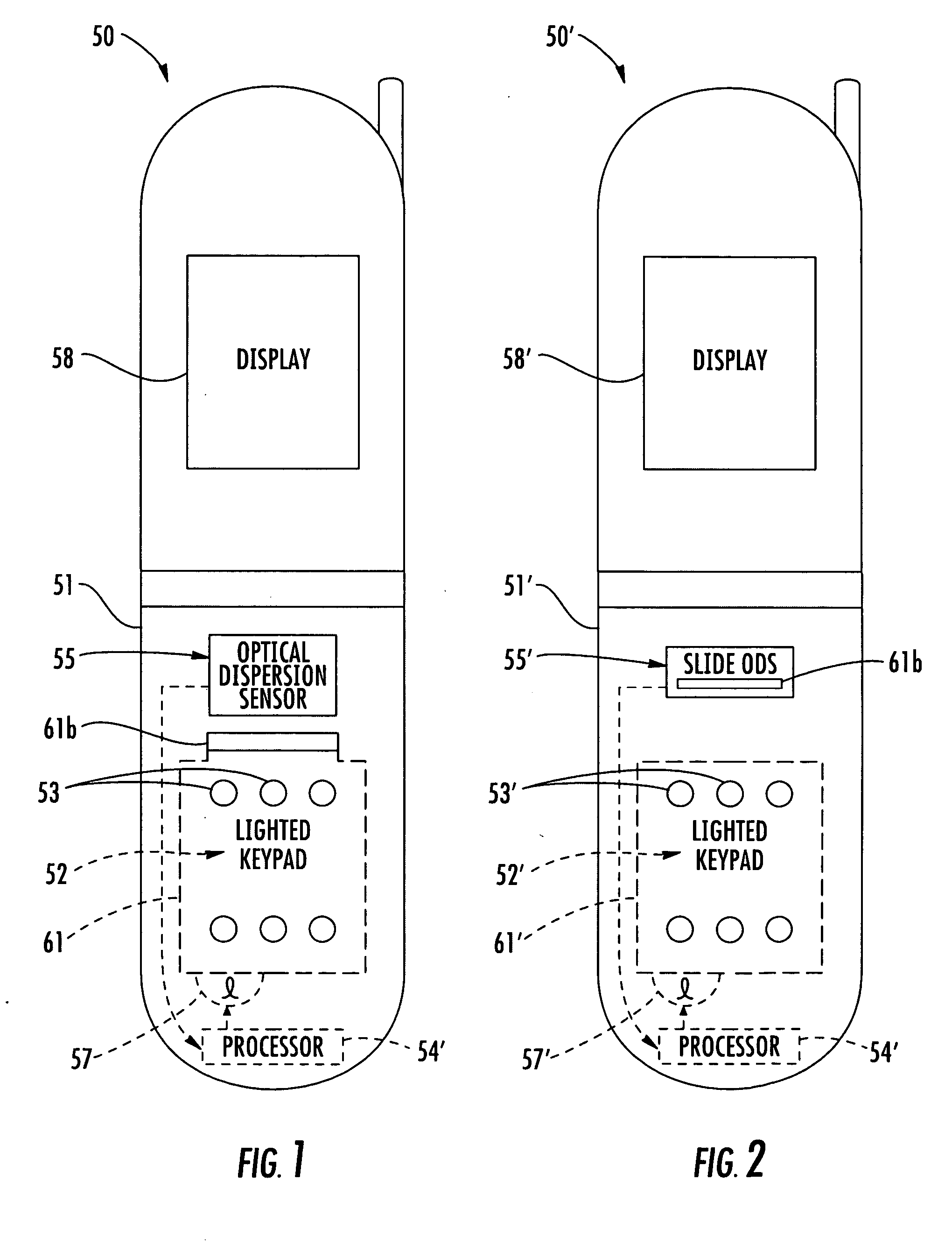
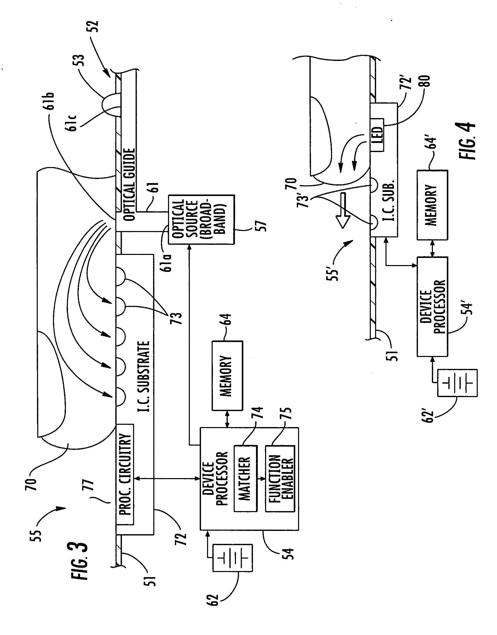
[0046] Referring initially to FIGS. 1-6, optical dispersion finger sensing as a biometric characteristic is first described. With particular reference to FIGS. 1 and 3, the electronic device is in the exemplary form of a cellular telephone 50 that includes a portable housing 51. The portable housing 51 carries an optical dispersion finger sensor 55, and a lighted keypad 52 ...


PUM


Abstract

A multi-biometric finger sensor may include at least one optical dispersion sensing pixel on an integrated circuit substrate for sensing dispersed light from the user's finger, and at least one other finger biometric characteristic sensor on the integrated circuit substrate for sensing a finger biometric characteristic different than the dispersed light from the user's finger. The sensor may also include a processor connected to the at least one optical dispersion sensing pixel and the at least one other finger biometric characteristic sensor.

Description

CROSS-REFERENCE TO RELATED APPLICATIONS [0001] This application claims benefit, under 35 U.S.C. 119(e), from U.S. Provisional Application Ser. No. 60 / 500,475, filed Sep. 5, 2003 and U.S. Provisional Application Ser. No. 60 / 536,305 filed Jan. 14, 2004, the entire disclosures of which are incorporated herein by reference.FIELD OF THE INVENTION [0002] The present invention relates to biometric sensing, and, more particularly to biometric sensing using integrated circuit biometric sensors and associated methods. BACKGROUND OF THE INVENTION [0003] Fingerprint sensing and matching is a reliable and widely used technique for personal identification or verification. In particular, a common approach to fingerprint identification involves scanning a sample fingerprint or an image thereof and storing the image and / or unique characteristics of the fingerprint image. The characteristics of a sample fingerprint may be compared to information for reference fingerprints already in a database to det...

Claims


Application Information

Patent Timeline
Patent Type & Authority Applications(United States)
IPC IPC(8): G06K9/00
CPCG06K9/00013G06K9/0002G06K9/00885G06K9/0004G06K9/0012G06K9/00026G06V40/1335G06V40/1394G06V40/1318G06V40/1306G06V40/10
Inventor SETLAK, DALE R.JONES, RICHARD J.FRANZA, GORDON S.
Owner APPLE INC
Learn More