Laser capture microdissection optical system

a technology of optical system and laser, which is applied in the field of inverted microscope, can solve the problems of incongruity of film property, time-consuming, and inconvenient prior-art methods for extracting cells of interest from surrounding tissue, and achieves the effects of reducing the number of incisions, and improving the quality of the incision

Inactive Publication Date: 2001-04-10
LIFE TECH CORP
View PDF87 Cites 93 Cited by
  • Summary
  • Abstract
  • Description
  • Claims
  • Application Information

AI Technical Summary

Benefits of technology

A laser capture microdisection instrument and / or method representing an embodiment of the invention can be cost effective and advantageous for at least the following reasons. The invention will replace current methods with better technology that allows for more accurate and reproducible results. The invention can be used to provide a low cost injection molded polymer disposable that integrates a laser capture microdissection transfer film into the interior surface of an analysis container such as a microcentrifuge tube (e.g., an EPPENDORF.TM. tube).All publications, patent applications, and issued patents mentioned in this application are hereby incorporated herein by reference in their entirety to the same extent as if each individual publication, application, or patent was specifically and individually indicated to be incorporated in its entirety by reference.All the disclosed embodiments of the invention described herein can be realized and practiced without undue experimentation. Although the best mode of carrying out the invention contemplated by the inventors is disclosed above, practice of the invention is not limited thereto. It will be manifest that various additions, modifications and rearrangements of the features of the invention may be made without deviating from the spirit and scope of the underlying inventive concept. Accordingly, it will be appreciated by those skilled in the art that the invention may be practiced otherwise than as specifically described herein.For example, the individual components need not be formed in the disclosed shapes, or assembled in the disclosed configuration, but could be provided in virtually any shape, and assembled in virtually any configuration. Further, the individual components need not be fabricated from the disclosed materials, but could be fabricated from virtually any suitable materials. Further, although the LCM instrument disclosed herein is described as a physically separate module, it will be manifest that the LCM instrument may be integrated into other apparatus with which it is associated. Furthermore, all the disclosed elements and features of each disclosed embodiment can be combined with, or substituted for, the disclosed elements and features of every other disclosed embodiment except where such elements or features are mutually exclusive.It will be manifest that various additions, modifications and rearrangements of the features of the invention may be made without deviating from the spirit and scope of the underlying inventive concept. It is intended that the scope of the invention as defined by the appended claims and their equivalents cover all such additions, modifications, and rearrangements. The appended claims are not to be interpreted as including means-plus-function limitations, unless such a limitation is explicitly recited in a given claim using the phrase "means-for." Expedient embodiments of the invention are differentiated by the appended subclaims.

Problems solved by technology

The problem has been that there has been no satisfactory prior-art method to extract the cells of interest from the surrounding tissue.
Most investigators consider both approaches to be tedious, time-consuming, and inefficient.
Another likely role for the technique is in recording the patterns of gene expression in various cell types, an emerging issue in medical research.
This property of the film may be in conflict with a desire to select film thickness for other reasons.
The organic dyes which are used to alter the absorption characteristics of the films may have detrimental photochemistry effects in some cases.
This could result in contamination of LCM samples.

Method used


Image

  • Laser capture microdissection optical system
  • Laser capture microdissection optical system
  • Laser capture microdissection optical system

Examples


Embodiment Construction

The invention and the various features and advantageous details thereof are explained more fully with reference to the nonlimiting embodiments that are illustrated in the accompanying drawings and detailed in the following description. Descriptions of well known components and processing techniques are omitted so as not to unnecessarily obscure the invention in detail.

The entire contents of U.S. Ser. No. 60 / 037,864, filed Feb. 7,1997 entitled "Laser Capture Microdissection Device," (Docket No. ARCT-002); U.S. Ser. No. 08 / 797,026, filed Feb. 7, 1997; U.S. Ser. No. 08 / 800,882, filed Feb. 14, 1997; U.S. Ser. No. 60 / 060,731, filed Oct. 1, 1997; and U.S. Ser. No. 60 / 060,732, filed Oct. 1, 1997 are hereby expressly incorporated by reference into the present application as if fully set forth herein.

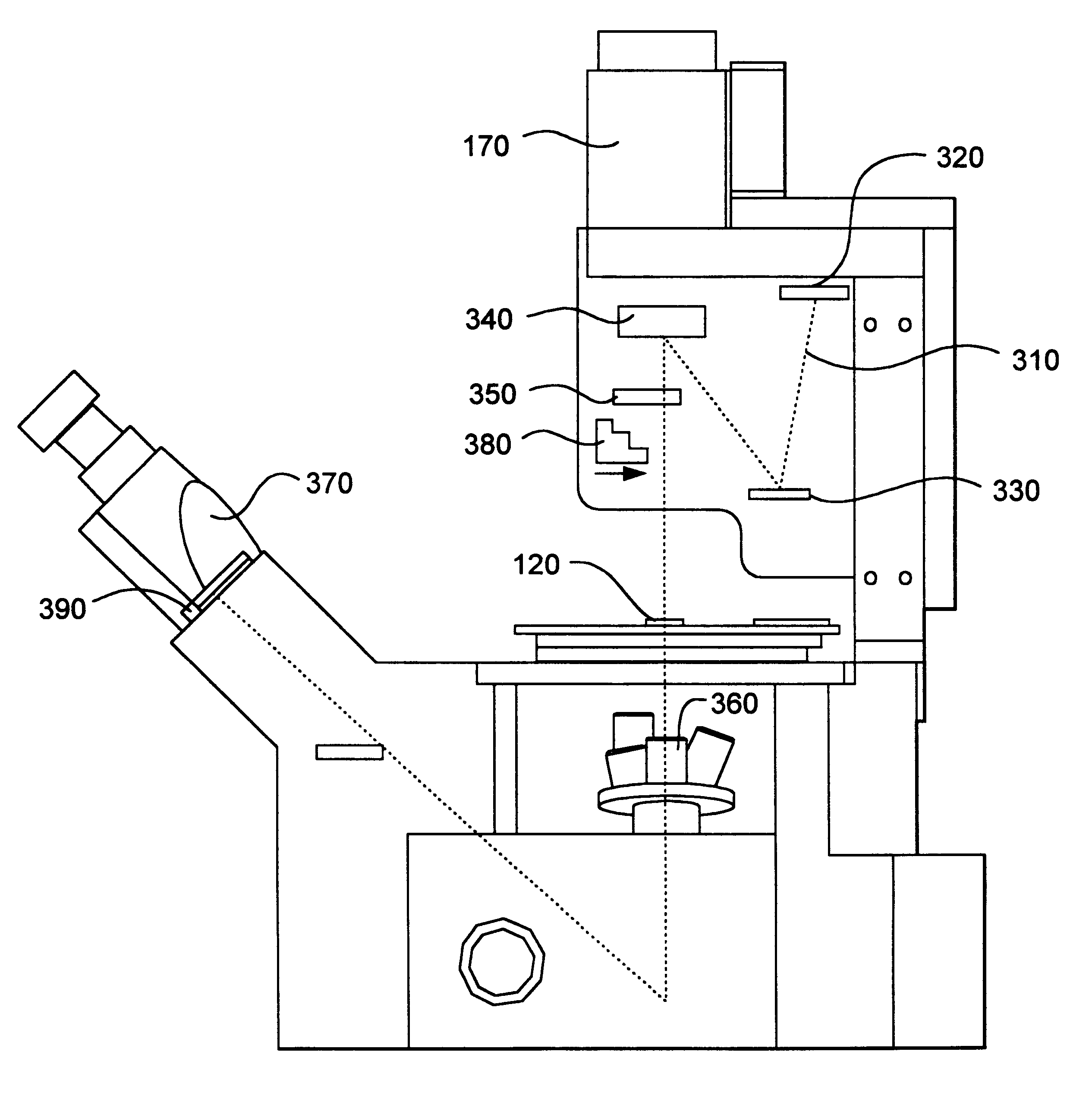
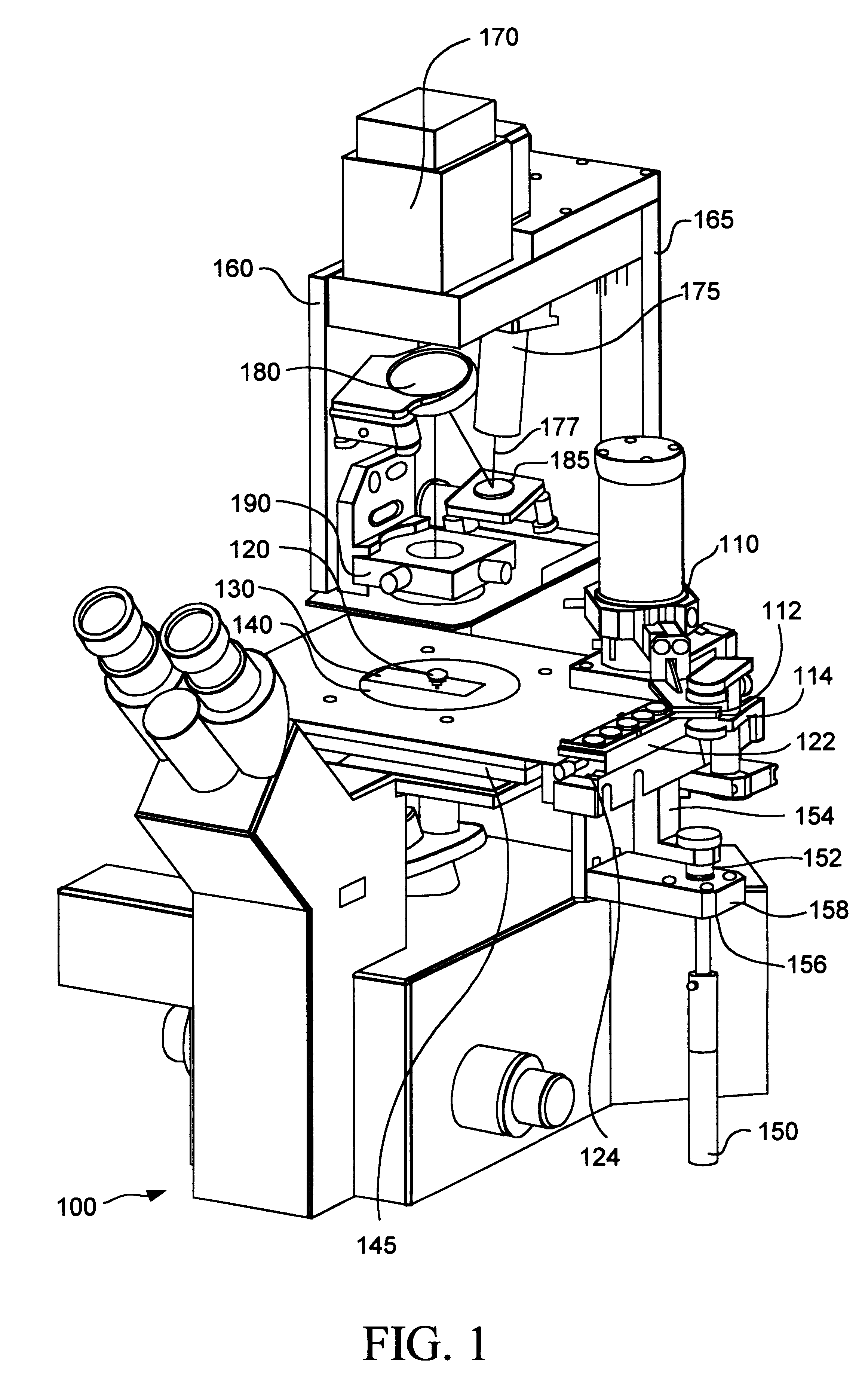
Turning to FIG. 1, a perspective view of an inverted microscope 100 for laser capture microdissection (LCM) is depicted. The inverted microscope 100 includes a variety of subsystems, particularl...


PUM

PropertyMeasurementUnit
thickaaaaaaaaaa
melting pointaaaaaaaaaa
wavelengthaaaaaaaaaa

Abstract

Systems and methods for laser capture microdissection are disclosed. An inverted microscope includes an illumination / laser beam delivery system that is adapted to both illuminate a sample and provide energy for laser capture microdissection of the sample. The systems and methods provide the advantages of increased speed and much lower rates of contamination.

Description

1. Field of the InventionThe invention relates generally to the field of laser capture microdisection (LCM). More particularly, the invention relates to inverted microscopes that include specialized apparatus for performing LCM. Specifically, a preferred implementation of the invention relates to an inverted microscope that includes a cap handling subsystem, an illumination / laser optical subsystem, a vacuum chuck subsystem, and a manual joystick subsystem. The invention thus relates to inverted microscopes of the type that can be termed laser capture microdisection inverted microscopes.2. Discussion of the Related ArtDiseases such as cancer have long been identified by examining tissue biopsies to identify unusual cells. The problem has been that there has been no satisfactory prior-art method to extract the cells of interest from the surrounding tissue. Currently, investigators must attempt to manually extract, or microdissect, cells of interest either by attempting to mechanically...

Claims


Application Information

Patent Timeline
Patent Type & Authority Patents(United States)
IPC IPC(8): G01N1/28G02B21/32G02B21/26G02B21/34
CPCG01N1/2813G02B21/32G01N1/2806G01N1/286G01N2001/2833G01N2001/284
Inventor BAER, THOMAS M.ENRIGHT, MARK A.HEAD, DAVID F.TODD, CHRISTOPHER E.
Owner LIFE TECH CORP
Why Eureka
Try Eureka