
Image compressing apparatus and image compressing method

a compression apparatus and image technology, applied in the field of image compression, can solve the problems of large amount of operation for a long time and large size of processing circuits, and achieve the effects of reducing the time required for operation processing, high compression rate, and high accuracy

Inactive Publication Date: 2005-03-24
RICOH KK
View PDF18 Cites 27 Cited by
  • Summary
  • Abstract
  • Description
  • Claims
  • Application Information

AI Technical Summary

Benefits of technology

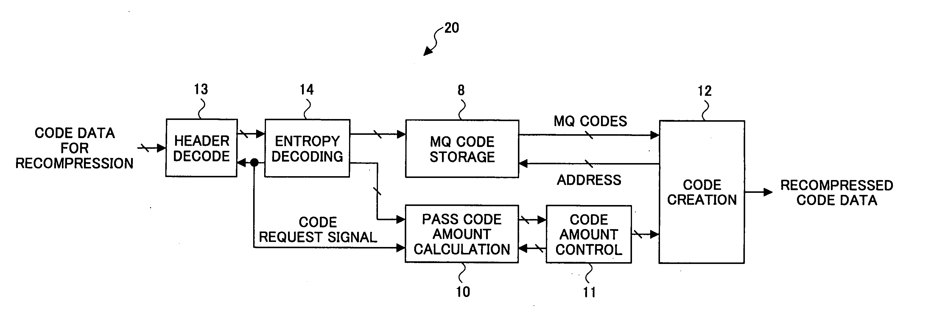
[0008] The present invention has an object to provide an image compressing apparatus which further generates data compressed and coded at a different compression rate, rapidly and easily, without decoding given code data to wavelet coefficients, and an image compressing method therefor.
[0010] In this configuration, the given code data is not completely decoded to image data, and, with the use of the given code data, it is possible to create code data which is one obtained from compressing image data, which is obtained from decoding the given code data, at a higher compression rate, without completely decoding the given code data. Thereby, it is possible to reduce a time required for the operation processing.
[0012] In this configuration, with the use of the given code data, it is possible to create code data which is one obtained from compressing and coding image data obtained from decoding the code data, at a higher compression rate at high accuracy, without completely decoding the given code data. Thereby, it is possible to reduce a time required for the operation processing.
[0014] In this configuration, the given code data, which is one once coded according to JPEG2000, is not completely decoded to image data, and, with the use of the given code data, it is possible to create code data which is one obtained from compressing image data, which is obtained from decoding the given code data, then at a higher compression rate. Thereby, it is possible to reduce a time required for the operation processing.
[0018] In this configuration, with the use of given code data, it is possible to create code data which is one obtained from compressing and coding image data obtained from decoding the code data, at a higher compression rate at high accuracy, without completely decoding the given code data. Thereby, it is possible to reduce a time required for the operation processing.

Problems solved by technology

However, in this case, a large amount of operation for a long time may be required, and also, a large size of processing circuit may be required accordingly.

Method used


Image

  • Image compressing apparatus and image compressing method
  • Image compressing apparatus and image compressing method
  • Image compressing apparatus and image compressing method

Examples


first embodiment

[0033] (2) First Embodiment

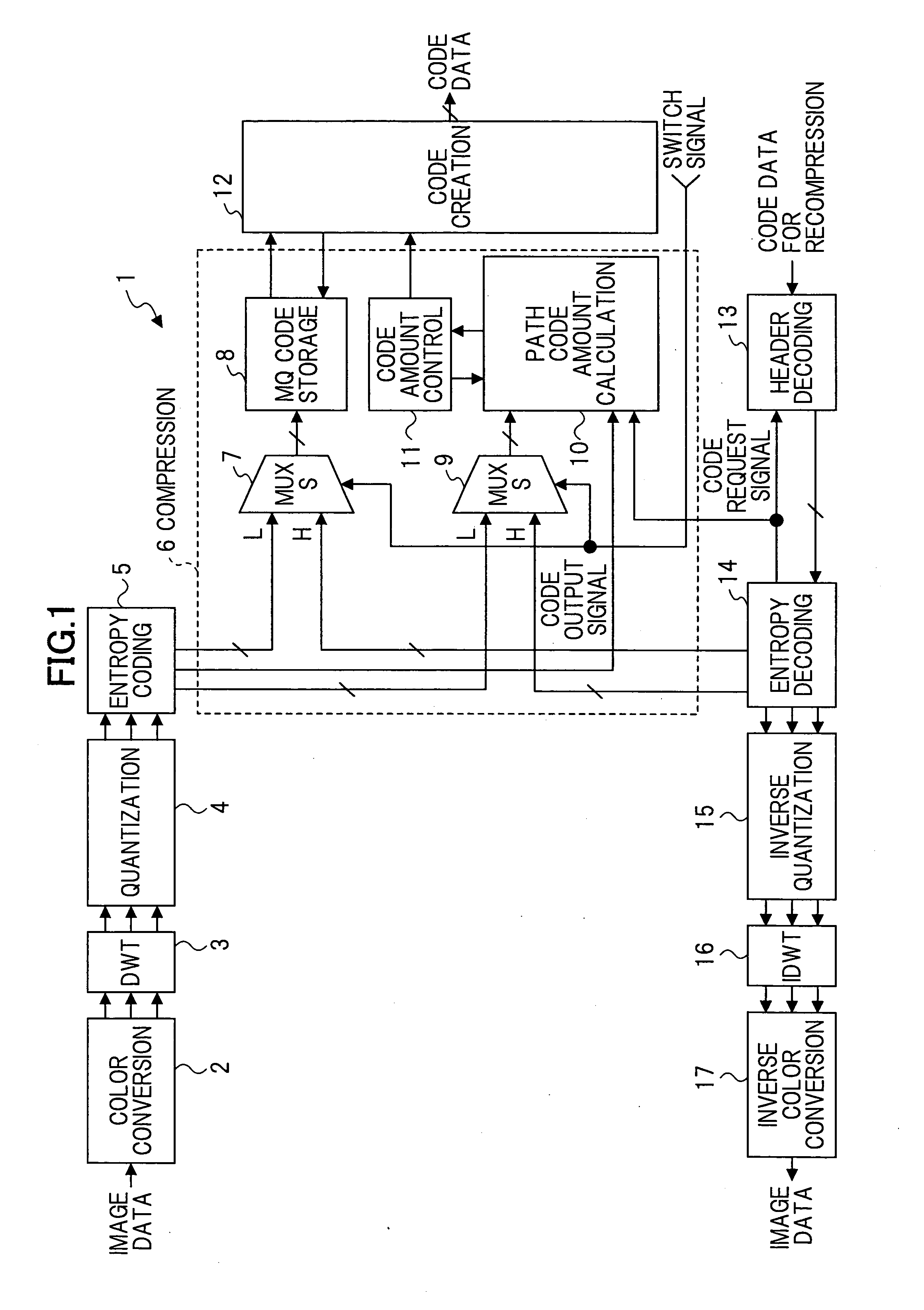
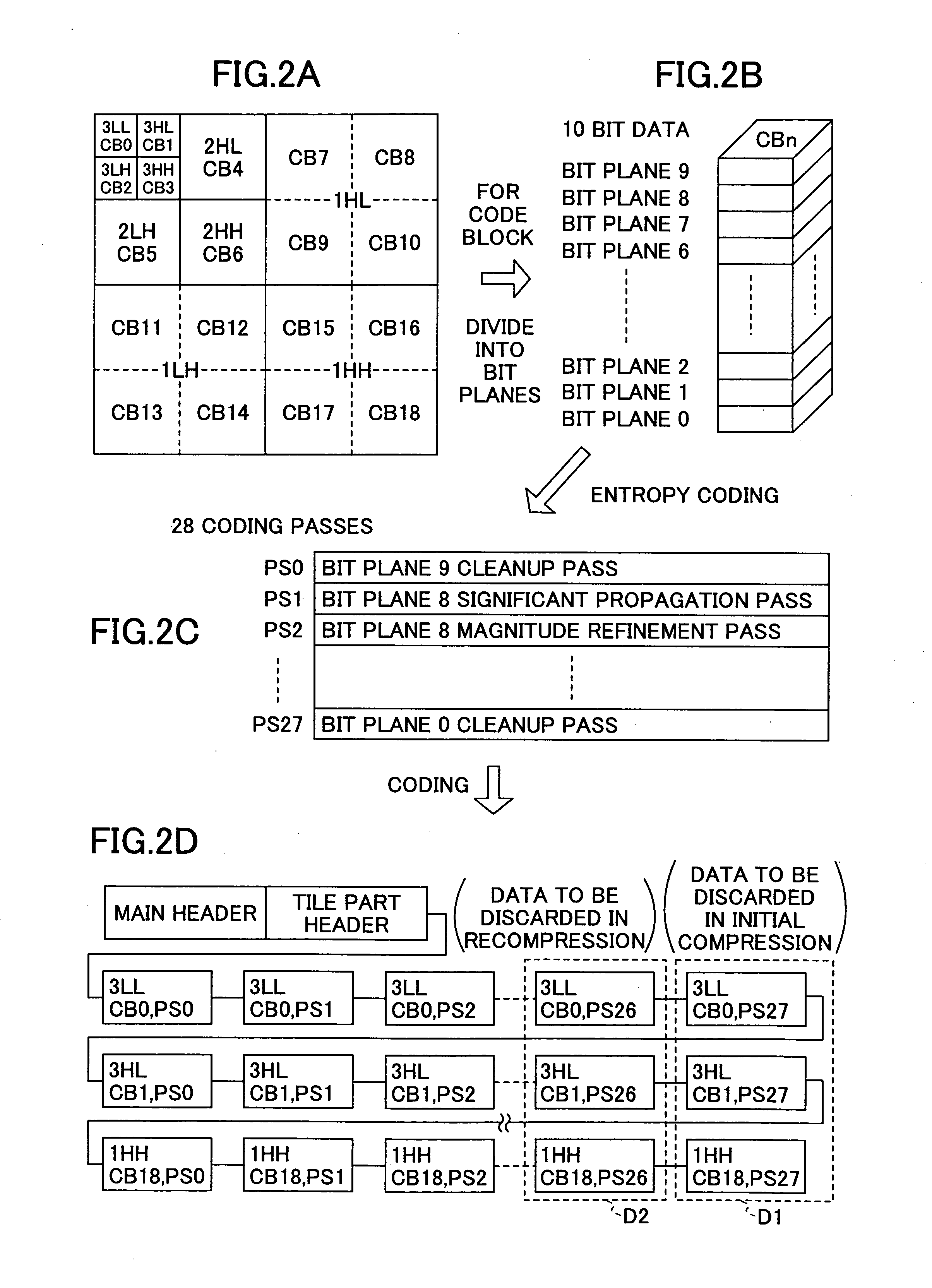
[0034] An image compressing apparatus according to a first embodiment of the predetermined is described next with reference to the figures. FIG. 1 shows a configuration of the image compressing apparatus 1 according to the first embodiment. The image compressing apparatus 1 has the above-mentioned recompressing function, and also, a function of coding image data according to JPEG2000, and a function of decoding code data reversely. FIG. 2 illustrates a general concept of image data compression and coding processing carried out by the image compressing apparatus 1. The image compressing apparatus 1 includes, as shown, a color conversion part 2, a DWT part 2, a quantization part 3, an entropy coding part 5, a compression part 6, a code creation part 12, a header decode part 13, an entropy decoding part 14, an inverse quantization part 15, an IDWT part 16 and an inverse color conversion part 17.

[0035] For the purpose of easy understanding of the processing c...


PUM


Abstract

From given code data, a first total data amount of codes is calculated for each processing unit. A second total data amount of codes is calculated for each processing unit from the first data amount of codes for each processing unit, which second data amount is a data amount obtained when image data obtained from decoding the code data is again compressed and coded at a higher compression rate. A re-compressed code data is obtained from updating the additional information to information for the re-compressed state, and reading the data of codes for each processing unit from a memory for the second total data amount in a predetermined manner.

Description

BACKGROUND OF THE INVENTION [0001] 1. Field of the Invention [0002] The present invention relates to an image compressing apparatus which performs compressing and coding of image data after performing frequency analysis and, in particular, to an image compressing apparatus performing compressing and coding of image data according to JPEG2000 for example, and an image compressing method therefor. [0003] 2. Description of the Related Art [0004] JPEG2000 is known as a coding method suitable for handling a high definition image. In coding processing according to JPEG2000, given image data is converted into data of respective color components of Y, Cb and Cr in color conversion processing. After that, two-dimensional discrete wavelet transform (DWT), which is a first method of frequency analysis, is performed on the data of each color component. For example, two-dimensional discrete wavelet transform in a level 2 is applied, and thus, wavelet coefficients in respective subbands, i.e., 3L...

Claims


Application Information

Patent Timeline
IPC IPC(8): G06K9/36H03M7/40H04N1/41H04N19/34H04N19/40H04N19/423H04N19/48H04N19/60H04N19/635H04N19/91
CPCH04N19/70H04N19/149H04N19/647H04N19/40H04N19/184H04N19/42H04N19/132
Inventor SATO, YUTAKA
Owner RICOH KK
Learn More