High figure of merit dispersion compensating fiber for standard single mode fiber and transmission system utilizing same

a technology of optical fiber and high merit, applied in the field of optical fiber, can solve problems such as loss of insertion

Inactive Publication Date: 2005-03-24
CORNING INC
View PDF34 Cites 15 Cited by
  • Summary
  • Abstract
  • Description
  • Claims
  • Application Information

AI Technical Summary

Problems solved by technology

As the length of dispersion compensating fiber required to compensate for the dispersion of the transmission fiber increases, so does the attenuation contributed thereby, and, thus, so does insertion loss.

Method used


Image

  • High figure of merit dispersion compensating fiber for standard single mode fiber and transmission system utilizing same
  • High figure of merit dispersion compensating fiber for standard single mode fiber and transmission system utilizing same
  • High figure of merit dispersion compensating fiber for standard single mode fiber and transmission system utilizing same

Examples


experimental examples

Several examples of the dispersion compensating fiber 20 in accordance with the invention were actually manufactured and tested. Optical properties of experimental Examples 1 and 2 are illustrated in Table 5 below; the profiles of which are shown in FIGS. 13 and 14, respectively.

TABLE 5Experimental ExamplesExample #Ex. 1Ex. 2FIG. #Dispersion @−123.3−128.81550 nm(ps / nm / km)Dispersion Slope @−0.420−0.4761550 nm(ps / nm2 / km)Kappa @2932711550 nm(nm)Mode Field Diameter @5.155.171550 nm(μm2)Pin Array @17.727.71550 nm(dB) - predictedLateral Load @1.452.321550 nm(dB / m) - predictedAttenuation @0.4060.4221550 nm(dB / km)FOM @3043051550 nm

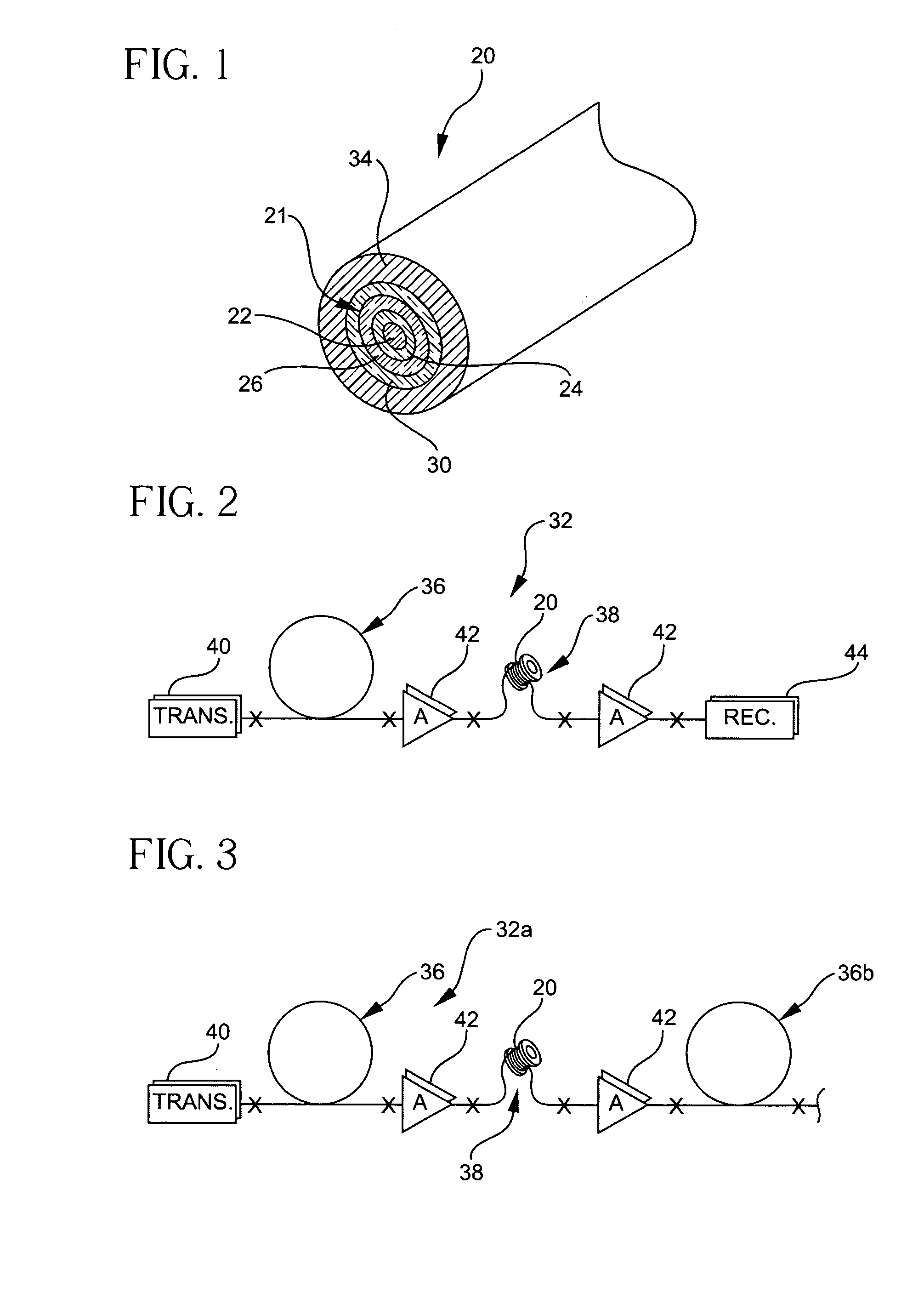
FIGS. 2 and 3 illustrate optical transmission systems 32, 32a employing the dispersion compensating fiber 20 according to the embodiments of the invention described herein. The systems 32, 32a include an optical signal transmitter 40, and a transmission fiber 36 optically coupled to, and in optical communication with, the transmitter 40. The transmission fiber ...


PUM


Abstract

A dispersion compensating optical fiber that includes a segmented core having a central core segment, a moat segment, and a ring segment wherein the ring segment is preferably offset from the moat outer radius, r2, by a ring offset, Xo, greater than 0.4 μm. The refractive index profile is selected to provide a total dispersion at 1550 nm of between about −120 and −145 ps / nm / km, and a total dispersion slope at 1550 nm of between about −0.36 and −0.56 ps / nm2 / km. The refractive index profile is preferably further selected to provide a kappa, defined as the total dispersion at 1550 nm divided by the dispersion slope at 1550 nm, of between about 250 and 320 nm. Optical transmission systems including the present invention dispersion compensating optical fiber which have residual dispersion less than ± 15 ps / nm per 100 km of standard single mode transmission fiber are also disclosed.

Description

BACKGROUND OF THE INVENTION 1. Field of the Invention The present invention relates generally to optical fiber, and particularly to dispersion compensating optical fibers and systems employing same. 2. Technical Background Increased demand for higher bit transmission rates has resulted in a large demand for optical transmission systems that can control and minimize dispersion effects. Analysis of common optical transmission systems indicates that while optical transmission systems can tolerate fairly large amounts of residual dispersion at 10 Gbit / second, these systems can tolerate only small amounts of residual dispersion at higher transmission rates of about 40 Gbit / second without causing unwanted signal distortion. Therefore, it is of the utmost importance to accurately control dispersion in such high bit-rate optical transmission systems across the entire wavelength band of interest. Moreover, dispersion control becomes increasingly important as the transfer rate increases. ...

Claims


Application Information

Patent Timeline
Patent Type & Authority Applications(United States)
IPC IPC(8): G02B6/036
CPCG02B6/02004G02B6/03677G02B6/0228G02B6/02261G02B6/028G02B6/036
Inventor HEBGEN, PETER G.MISHRA, SNIGDHARAJ K.
Owner CORNING INC
Why Eureka
Try Eureka