

Image forming device
a technology of forming device and forming plate, which is applied in the direction of electrographic process apparatus, instruments, printing, etc., can solve the problem of reducing standby power
- Summary
- Abstract
- Description
- Claims
- Application Information
AI Technical Summary
Benefits of technology
Problems solved by technology
Method used
Image

Examples
Embodiment Construction
[0001] 1. Field of the Invention
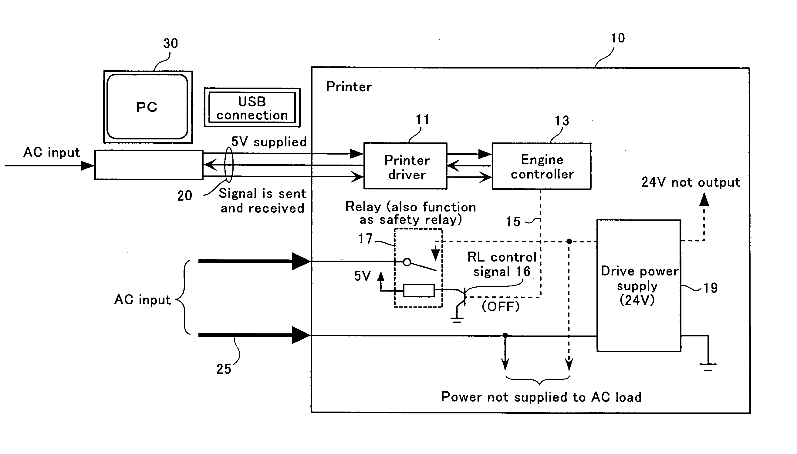
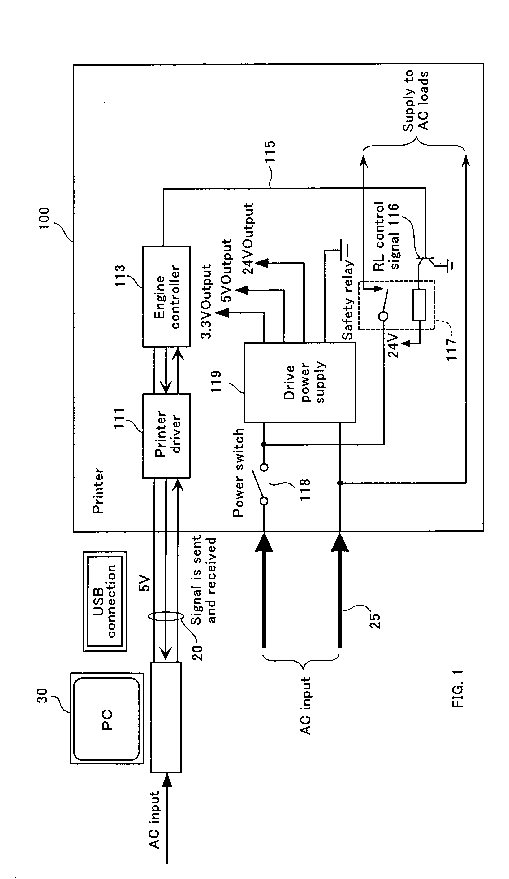
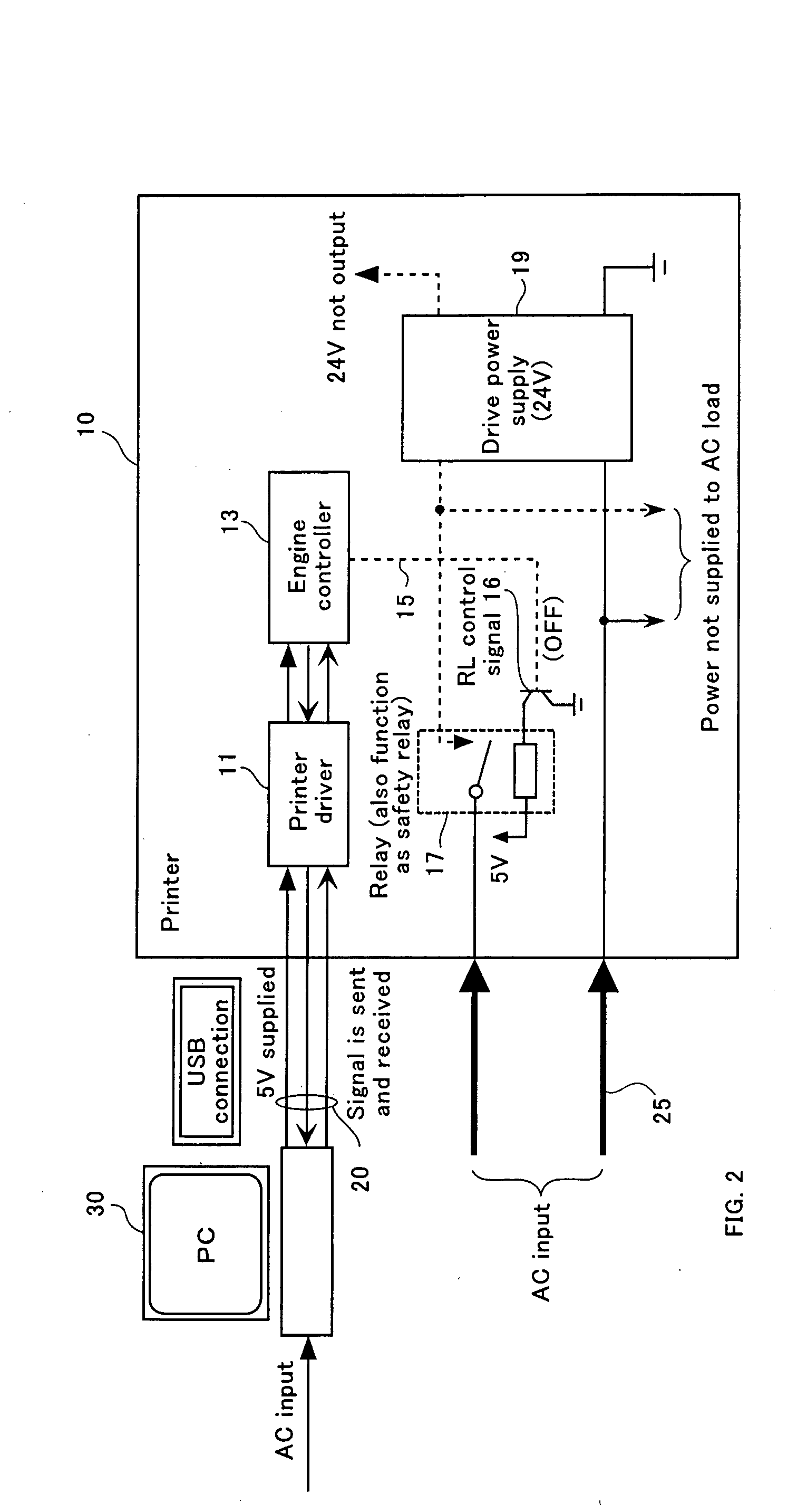
[0002] The present invention relates to an image forming device, such as a printer, that has a serial communication interface as an external terminal for receiving signals from an external device, for example, a USB (Universal Serial Bus) used for connection to an external device such as a PC (Personal Computer).
[0003] 2. Related Art
[0004] Conventionally, an image forming device typically has connection terminals, such as a Centronics parallel interface terminal, USB terminal, or network LAN terminal, as terminals for connection to a PC. Increasingly, more and more low-cost image forming devices with only an easy-to-connect USB terminal are used.
[0005] An image scanner, typically only with a USB terminal as the connection terminal for connection to a PC, sometimes does not have a power supply in the scanner but receives power from the PC via the connected USB terminal for operation.
[0006] The power supplied to a device via the USB power line is n...
PUM
 Abstract
Description
Claims
Application Information