Speed hump device

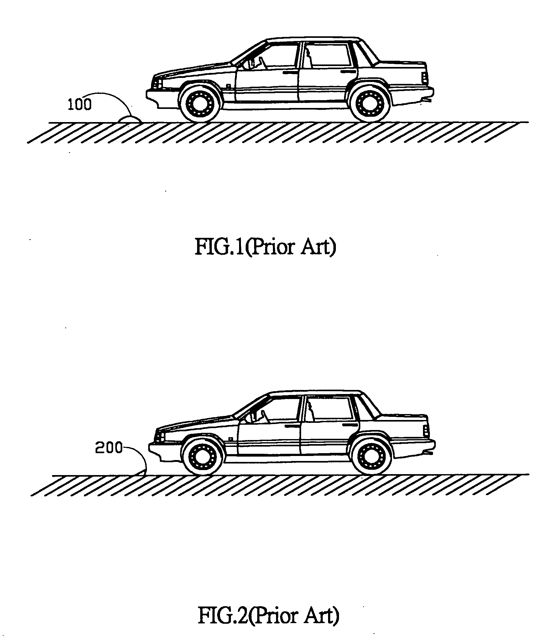
a technology of speed hump and hump, which is applied in the direction of roads, roads, construction, etc., can solve the problems of serious harm to the running car, the traditional speed hump b>100/b> is not suitable for most traffic roads, and the harm to the motor vehicle, so as to improve the disadvantages of the traditional speed hump

Inactive Publication Date: 2005-03-24
YANG CHIH CHENG
View PDF9 Cites 28 Cited by
  • Summary
  • Abstract
  • Description
  • Claims
  • Application Information

AI Technical Summary

Benefits of technology

[0007] It is one of objectives of the present invention to provide a speed hump

Problems solved by technology

In general, although different traditional speed humps could be designed to any kind of figure and made of different materials, they have all motor vehicles run thereon suffered a uncomfortable impact effect weather the speed of the motor vehicles are fast or slow, and that is real a torment to a diver who obey the traffic rule and drive slowly, specially, slower than a demanded threshold speed, further, that also causes harm to the motor vehicles.
Therefore, the traditional speed hump 100 is not suitable for most traffic roads.
However, the traditional traffic hump 200 could not be used to be a speed hump, as the traditional speed hump 100 shown in FIG. 1, since the sharp figure of the traditional traffic hump 200 will cause serious harm to a running car.
Due to the disadvantages of the traditional speed humps mentioned abo

Method used


Image

  • Speed hump device
  • Speed hump device
  • Speed hump device

Examples


Embodiment Construction

[0039] The invention will be explained in detail in accordance with the accompanying drawings. It is necessary to illustrate that the drawings in the below could be in simplified forms and not drawn in proportion to the real cases. Further, the dimensions of the drawings are enlarged for explaining and understanding more clearly.

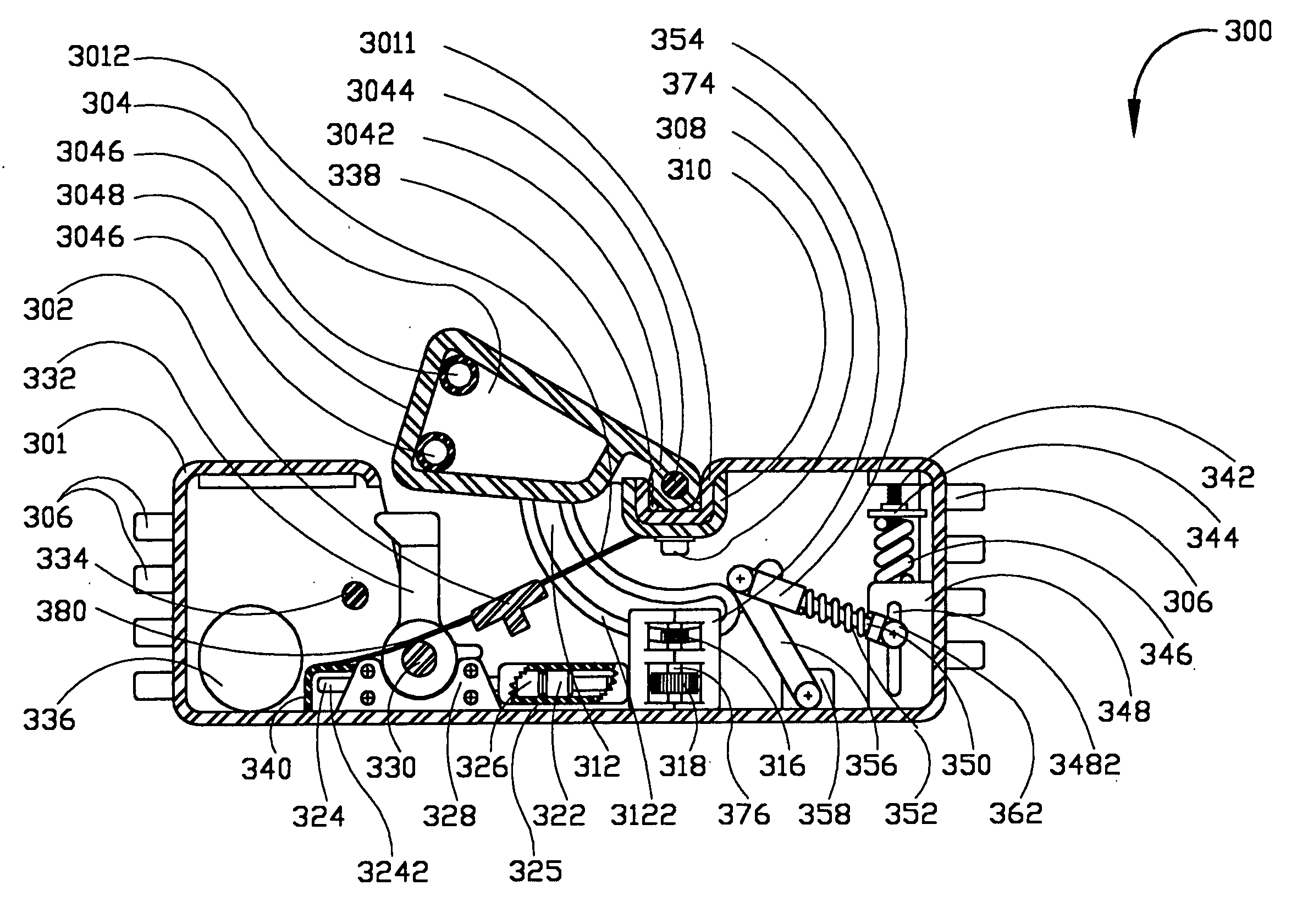
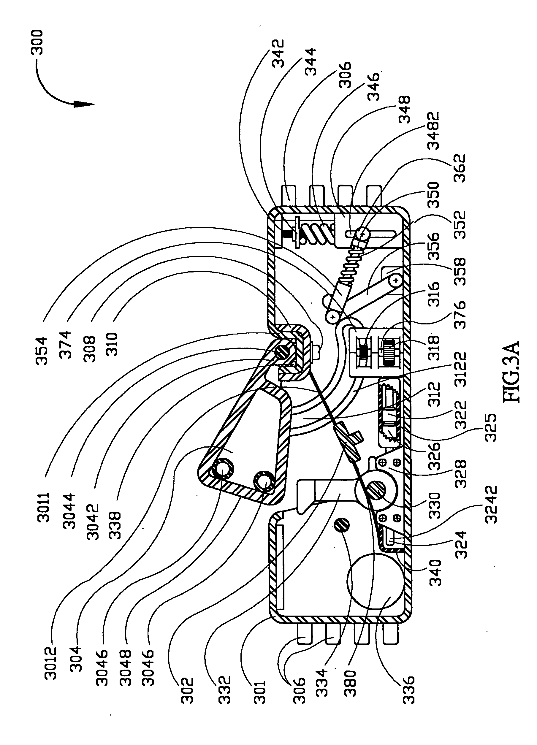
[0040] The present invention discloses a speed hump device for discouraging vehicles form exceeding a demanded threshold speed, one preferred embodiment of the present invention is shown as FIG. 3A. FIG. 3A is a transverse cross-section view of the preferred embodiment; FIG. 3F, FIG. 3G and FIG. 3H are respectively the top view, front view, and side view of the preferred embodiment. The preferred embodiment, a speed hump device 300 for motor vehicles, mainly includes four portions: a housing device as shown in FIG. 3B, a hump device as shown in FIG. 3C, a transmission device as shown in FIG. 3D and a rebound device as shown in FIG. 3E. And all the four port...


PUM


Abstract

A speed hump device for discouraging vehicles form exceeding a designed threshold speed is disclosed. The speed hump device mainly comprises: a housing device, whose figure is like a box, having a housing room therein and a opening thereon; a hump device with a hump member and a arc-shaped member pivoted on the housing device by a first pivot, the hump member can be rotated in and out the housing room from the opening about the first pivot; a transmission device including a gear set, a transmitting mechanism and a abutment member, wherein the arc-shaped member is engaged with one gear of the gear set; a rebound device used to push the hump member out the housing device when no extra force presses on the hump member. When a car passing through the speed hump device with a slow speed, e.g., below a threshold speed, the abutment member will be put down and the hump member can be depressed in the housing room by the wheels of the car, hence the hump member as a jolt will disappear and the car will traverse smoothly; on the contrary, if the speed of the car is over the threshold speed, the hump member will be still in the position out the housing room that a jolt will occur to cause a impact effect to the car. Additionally, the hump member of the speed hump device will have an impedimental effect to a car goes against the traffic flow direction. Moreover, it does not consume any additional energy to drive the speed hump device.

Description

BACKGROUND OF THE INVENTION [0001] 1. Field of the Invention [0002] The present invention relates to a speed hump device, and more particularly to a speed hump device for discouraging motor vehicles form exceeding a demanded threshold speed. [0003] 2. Description of the Prior Art [0004] One such known traditional speed hump 100, as shown in FIG. 1, is a so-called “sleeping policeman” including one or more raised portions as humps extending across, usually fully across, the “controlled” road or traffic surface. By the sufficient height of the raised portions, the traditional speed hump 100 causes noticeable impact or jolt effect to cars or other motor vehicles. In general, although different traditional speed humps could be designed to any kind of figure and made of different materials, they have all motor vehicles run thereon suffered a uncomfortable impact effect weather the speed of the motor vehicles are fast or slow, and that is real a torment to a diver who obey the traffic rul...

Claims


Application Information

Patent Timeline
IPC IPC(8): E01F9/529E01F13/12
CPCE01F13/126E01F9/047E01F9/529
Inventor YANG, CHIH-CHENG
Owner YANG CHIH CHENG
Why Eureka
Try Eureka