

Pulsed-neutron formation density
a technology of pulsed neutron and formation density, which is applied in the field of pulsed neutron density logging tools, can solve the problem that the bulk density measurement made with a pulsed neutron logging tool may not match the actual bulk density
- Summary
- Abstract
- Description
- Claims
- Application Information
AI Technical Summary
Problems solved by technology
Method used
Image

Examples
Embodiment Construction
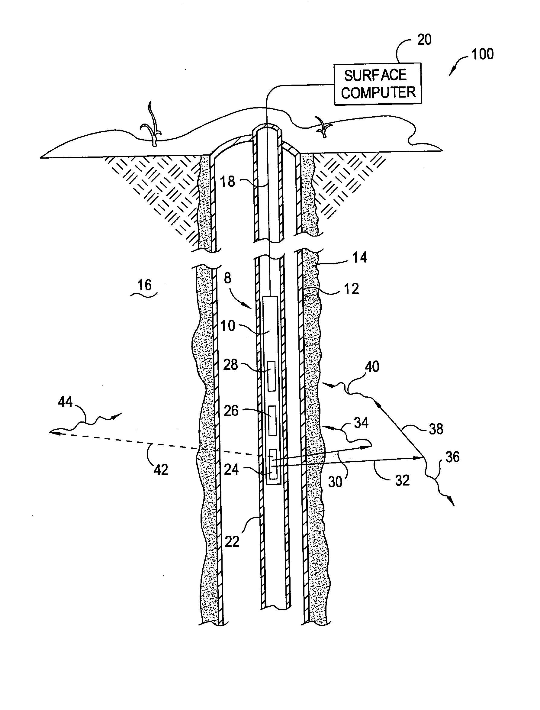
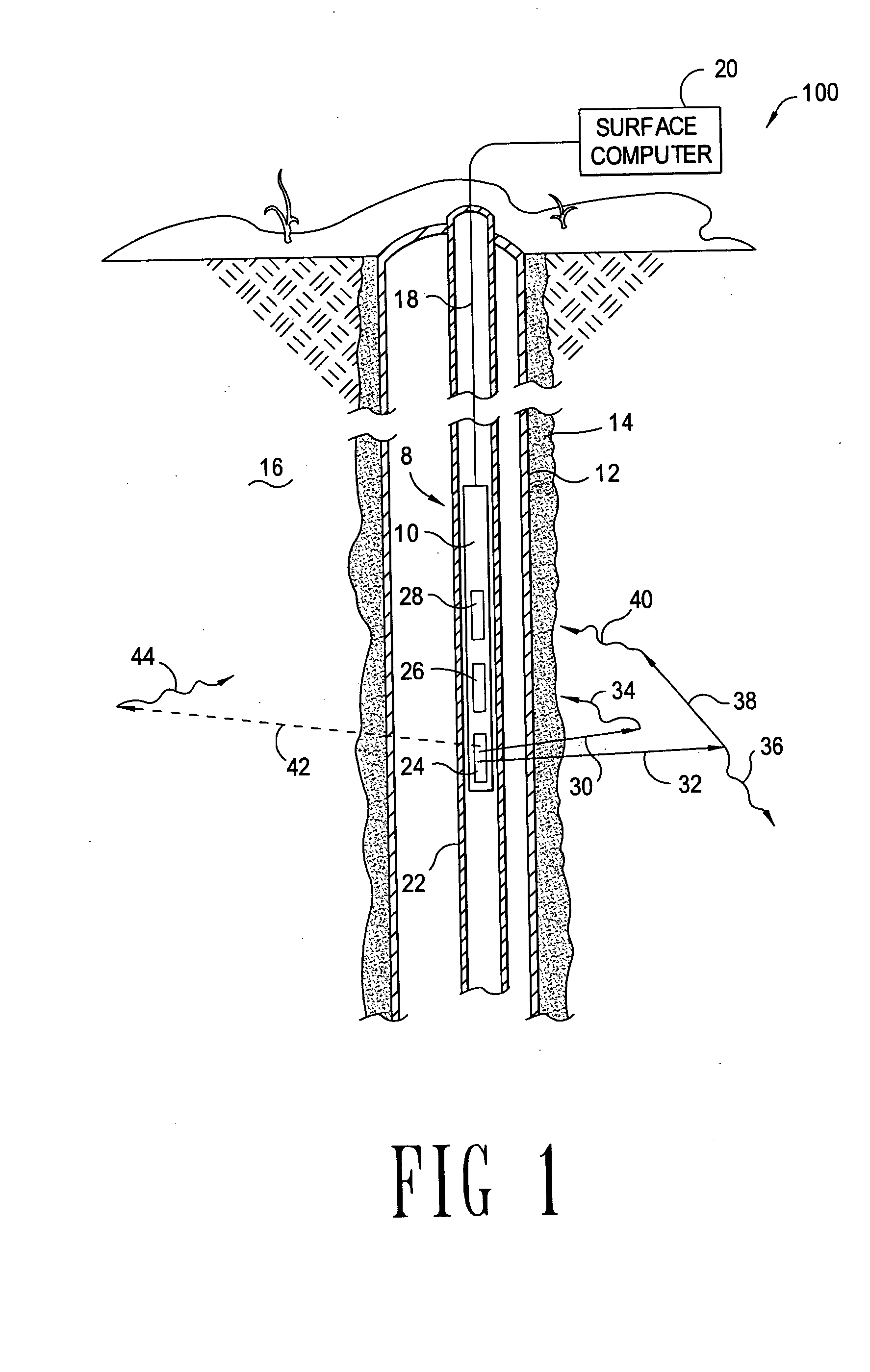
of the invention are directed to pulsed-neutron density logging tools. More particularly, embodiments of the invention are directed to pulsed-neutron density logging tools that compensate for neutron transport effects.
2. Background of the Invention
Pulsed-neutron logging tools may be used in cased boreholes, and in some situations pulsed-neutron logging tools may be operated within production tubing. Pulsed-neutron logging tools operate on the principle of releasing high energy neutrons, on the order of 14 Mega electron Volts (MeV) into the formation. The high energy neutrons inelastically collide with other particles and thereby create gamma rays (known as inelastic gamma rays). Some of the inelastic gamma rays created by the collisions make their way back to, and are detected by, gamma ray detectors on the logging tool. The ratio of received gamma rays between a detector close to the pulsed-neutron source (the near detector) and a detector at some distance from the pulsed-neutro...
PUM
 Abstract
Description
Claims
Application Information