On-site rail welding apparatus

a welding apparatus and rail technology, applied in metal working apparatus, manufacturing tools, roads, etc., can solve problems such as defects that cannot be destructed, defects that cannot be found using destructive methods, and internal defects of railroad rails manufactured

Inactive Publication Date: 2005-03-31
HOLLAND CO
View PDF29 Cites 26 Cited by
  • Summary
  • Abstract
  • Description
  • Claims
  • Application Information

AI Technical Summary

Benefits of technology

[0020] The aforementioned issues can be addressed by solutions offered by the instant welding apparatus. As more fully described below, the welding apparatus repairs a railroad rail defect in a portion of the rail and more preferably in the rail head or in the rail web, or in the rail head and rail web.

Problems solved by technology

Railroad rails may be manufactured with internal defects or, as a result of wear-and-tear or fatigue, develop defects.
These defects are found using non-destructive test methods.
The track is not designed to allow the rails to contract and expand in response to environmental temperature changes.
The ART must be controlled because too low of an ART can cause the rail to buckle when the CRT of the rail is too high and too high of an ART can cause the rail to pull apart when the CRT of the rail is too low.
Buckles and pull aparts cause unsafe conditions and can cause serious accidents.
Moreover, such welds are not clean as they can include numerous inclusions from the welding process.
The flash-butt welding process is typically more costly than a thermite process but produces a cleaner and stronger weld.
However, this method also requires the repair crew to transport a plug to the rail repair site and the section of the rail containing the defect away from the site.
This prevents the railroad from running revenue producing trains.
In the area of gas shielded arc welding of railroad rails, several approaches have been taught, although they have not necessarily met with functional success in the field.
This can, in turn, result in the migration of carbon from the rail as well as a change in microstructure and material properties.
Moreover, the welding process can introduce hydrogen (H2) into the final weld which has the effect of embrittling the weld material and causing a weld failure.

Method used


Image

  • On-site rail welding apparatus
  • On-site rail welding apparatus
  • On-site rail welding apparatus

Examples


Embodiment Construction

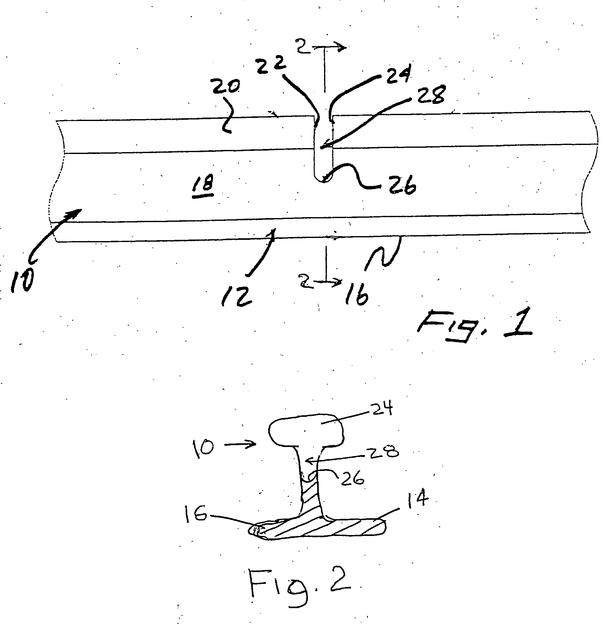
[0051]FIG. 1 illustrates a railroad rail 10 having a base 12 with opposed flanges 14, 16, an upstanding web 18 extending upward from the base 12 between the flanges 14, 16 and a head 20 at the top of the web. The use of our welding apparatus begins when a rail defect is identified and located, such as by using an ultrasonic rail-testing car and then removed to provide a slot or rail-void interface 28 that has opposing vertical walls 22 and 24 and a rounded base 26. The ultrasonic rail-testing car can precisely locate and mark the area of the rail containing the defect. Additionally, manual testing of the defect may further delineate the areas of the rail which contain the defect. For illustrative purposes we show that the ultrasonic testing confirmed that the defect is totally contained in the rail head 20 and web 18. The top portion of the rail is then removed, as more fully described below. Although this top portion is directed to the rail head and portion of the web, the top port...


PUM

PropertyMeasurementUnit
lengthaaaaaaaaaa
lengthaaaaaaaaaa
lengthaaaaaaaaaa

Abstract

An on site railroad rail welding repair apparatus wherein a railroad rail is an operating railroad track and a defect in the rail has been removed to provide a void and a rail-void interface while maintaining continuity of the rail having pair of cooling blocks which have an internal configuration to complement the rail, and an arc welder that fills the void with appropriate molten metal and causes the molten metal and the rail at the rail-void interface to bond. Also, a robotic welding apparatus and a weld containment apparatus engageable with the rail-void interface by movement having a pivotal and longitudinal component. Further, a mobile weld delivery unit delivering materials through an umbilical to a robotic welding apparatus having a welding device proximate the rail-void interface so that a weld can be made joining the rail-void interface.

Description

CLAIM OF PRIORITY [0001] This application is a continuation-in-part of our PCT Application PCT / US2003 / 02470 filed Aug. 8, 2003 claiming priority from our provisional application Ser. No. 60 / 402,184 filed Aug. 9, 2002.BACKGROUND [0002] 1. Field of the Invention [0003] The invention relates to a rail welding apparatus for repairing a railroad rail having a defect in the top portion of the rail wherein the defect is cut out to provide a rail void and rail-void interface and the apparatus welds the rail-void interface on site. [0004] 2. Description of Related Art [0005] Railroads have to maintain their track to ensure safe operation of trains. Some of this maintenance is centered on the repair of rail defects. Railroad rails may be manufactured with internal defects or, as a result of wear-and-tear or fatigue, develop defects. These defects are found using non-destructive test methods. The Federal Railway Administration (FRA) mandates periodic ultrasonic testing of railroad rails to loc...

Claims


Application Information

Patent Timeline
Patent Type & Authority Applications(United States)
IPC IPC(8): B23K9/00
CPCB23K2201/26B23K9/0026B23K2101/26
Inventor COOMER, DANIEL J.
Owner HOLLAND CO
Why Eureka
Try Eureka