
Recording material consumption control for an image forming apparatus

a technology recording material, which is applied in the field of recording material consumption control of image forming apparatus, can solve the problems of reducing image quality, excessive toner or ink consumption, and deterioration of toner or ink devices, so as to improve output image reproducibility and limit the amount of toner or ink

Active Publication Date: 2005-03-31
CANON KK
View PDF5 Cites 20 Cited by
  • Summary
  • Abstract
  • Description
  • Claims
  • Application Information

AI Technical Summary

Benefits of technology

The present invention has been made in consideration of the above situation, and has as its object to improve output image reproducibility while limiting the amount of toner or ink adhering per unit area.
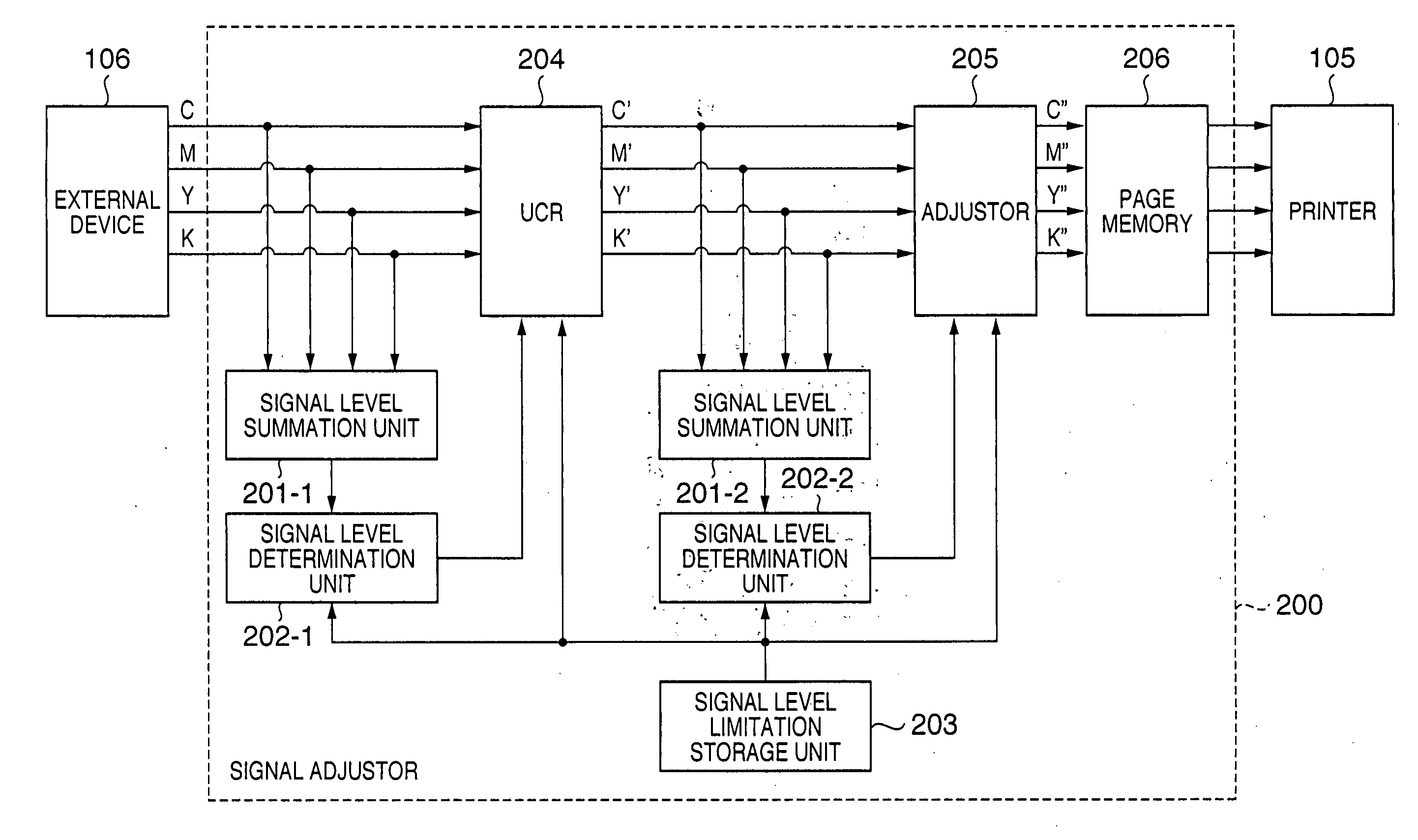
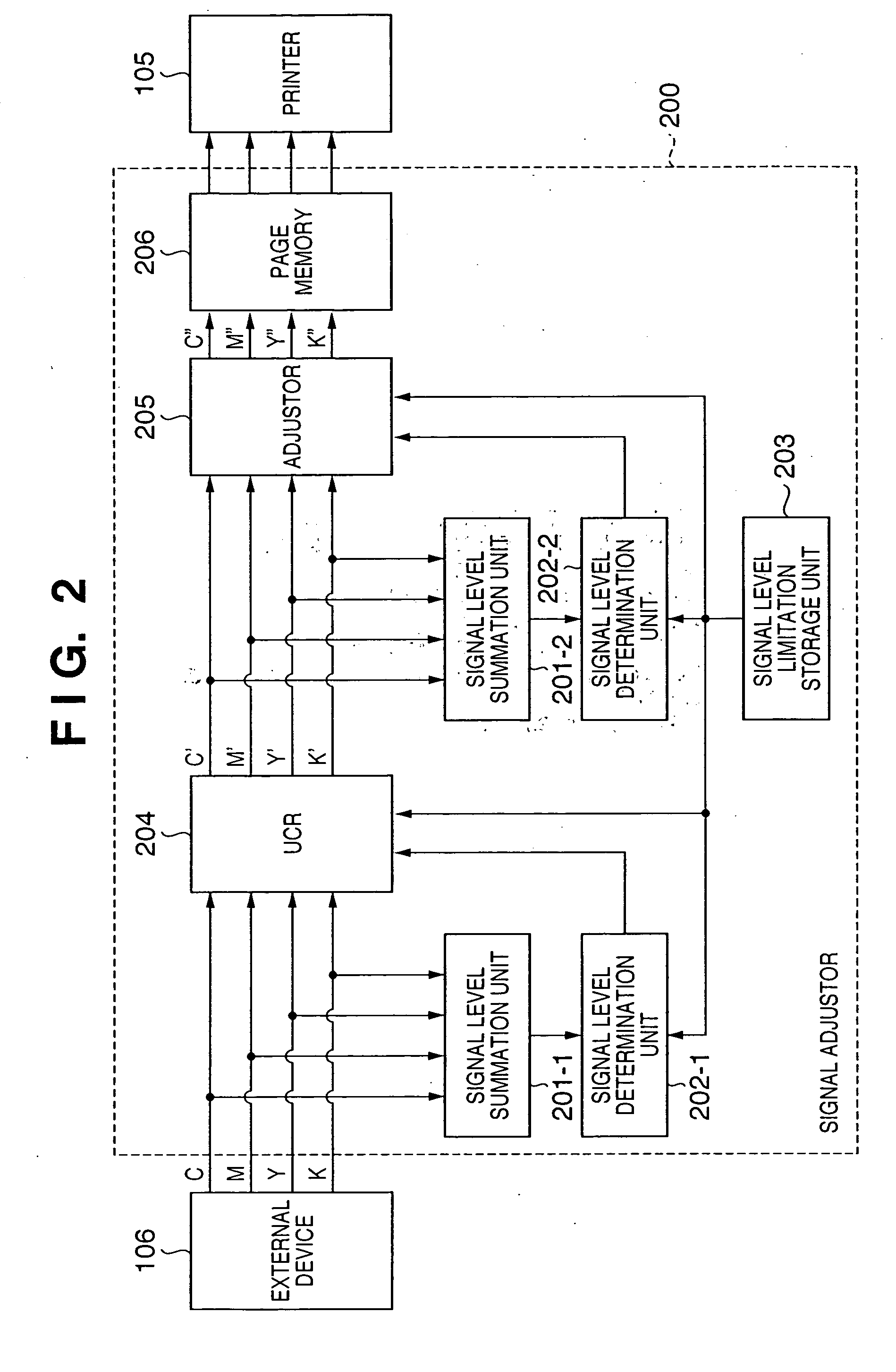
According to the present invention, the foregoing object is also attained by providing an image processing method that supplies an image signal to an image forming apparatus that forms an image on a recording medium using recording material, the image processing method comprising: inputting C, M, Y and K signals as image signals; reading out from a storage unit a limiting value of a sum of signal levels of image signals output to the image forming apparatus; comparing the limiting value and the sum of the signal levels of the input C, M, Y and K signals; replacing a predetermined level of C, M and Y signals with a K signal in an under color removal process when the sum of the signal levels of the input C, M, Y and K signals exceeds the limiting value; comparing the limiting value and the sum of the signal levels of the C, M, Y and K signals after undergoing the under color removal process; and reducing, where the sum after the under color removal process exceeds the limiting value, the C, M and Y signals after undergoing the under color removal process at an identical rate so as to reduce the sum after the under color removal process to less than the limiting value.

Problems solved by technology

In these cases, even though the amount of toner or ink consumed by each individual graphic object might be within the limiting value, there are nevertheless pixel data which exceed these limiting values in the print image data, which then lead to excess toner or ink consumption and cause the toner or ink device to deteriorate.
Further, when a process of reducing the amount of toner or ink, as described above, is carried out, the quality of the image declines, such as fainting of with the overall color of the printed matter output, and greater color changes than anticipated, and so forth.

Method used


Image

  • Recording material consumption control for an image forming apparatus
  • Recording material consumption control for an image forming apparatus
  • Recording material consumption control for an image forming apparatus

Examples


first embodiment

(First Embodiment)

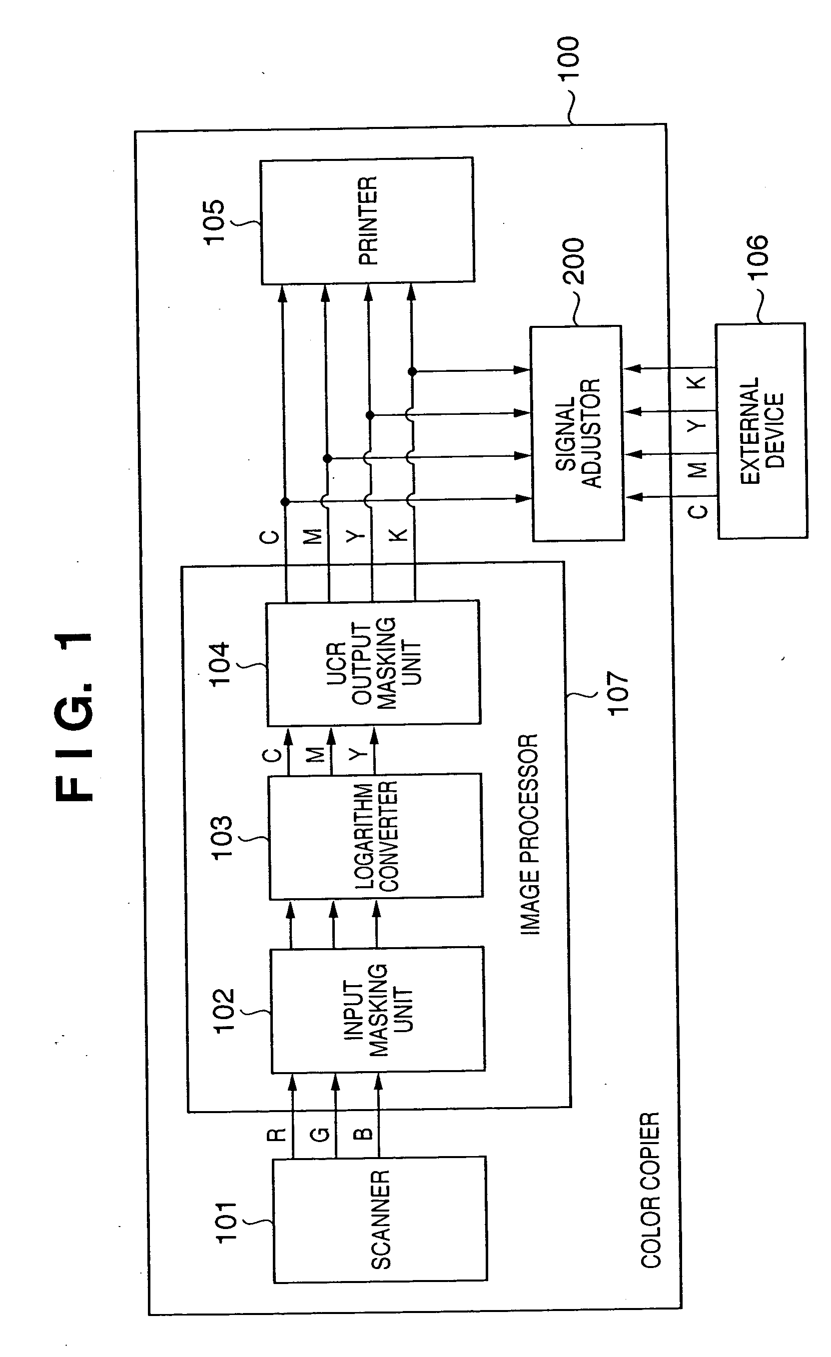
FIG. 1 is a block diagram showing an example of the construction of a color copier 100 according to the first embodiment of the present invention.

First, in a normal copy operation, RGB signals of an original image output from a scanner 101 are input and masked by an input masking unit 102 of an image processor 107, are logarithm-converted by a logarithm converter 103 and converted into C, M and Y (CMY) image signals. These CMY image signals are then subjected to under color removal and output masking processed by a UCR output masking unit 104, and output to a printer 105 as CMYK image signals.

In a normal copy operation, because the UCR amount and a masking coefficient are set at the UCR output masking unit 104 in order to keep the level of the image signals within the processing capacity of the printer 105, there is no input to the printer 105 of image signals with levels exceeding the processing capacity of the printer 105.

Next, a description is given of an ...

second embodiment

(Second Embodiment)

Next, a description is given of a second embodiment of the present invention with reference to FIG. 5.

In the second embodiment, the way in which the adjustment level α is calculated using the adjustor 205 (step S18) and the way in which the signals are calculated (step S19) are different from those of the first embodiment. Other than that, the same processes as shown in FIG. 3 are carried out in FIG. 5, including step S13 in FIG. 5 in which the same process as in step S3 in FIG. 3 is carried out. Therefore the same reference numerals are used and a description thereof is omitted here.

In the first embodiment in step S8 the adjustment level α is calculated using equation (6). On the other hand, the adjustment level a is calculated using equation (8) in the second embodiment (step S18).

α=C_Max / Sum—In′  (8)

In step S19, the signal value of signal K′ is also decreased at the same proportion as are the other signals C′, M′, Y′ using the calculated adjustment leve...

third embodiment

(Third Embodiment)

Next, a description is given of a third embodiment of the present invention.

In the third embodiment, the under color removal amount Ucr in step S13 in FIG. 5 is calculated using the following equation (9):

Ucr=Min((Sum—In−C_Max) / 2, R×Min(C,M,Y))  (9)

It should be noted that R indicates the under color removal level, which is either specified by the user or stored previously in the apparatus. Moreover, 0≧R≧1. However, Ucr=0 when the output results of the signal level determination unit 202-1 show that the signal level is within the limiting value.

In this method of calculating Ucr, in contrast to the first and second embodiments in which the amount of toner used is zero for any single color, the signal levels leave a minimum color at a constant proportion. Otherwise, the third embodiment is identical to the first embodiment and therefore a description thereof is omitted here.

FIGS. 7A-7C schematically express changes in CMYK signal levels due to processing by t...


PUM


Abstract

The present invention provides an image processing apparatus that supplies image signals to an image forming apparatus that forms an image on a recording medium using recording material. The apparatus includes a storage unit that stores a limiting value of a sum of signal levels of image signals output to the image forming apparatus, an input unit that inputs C, M, Y and K signals as image signals, a first comparison unit that compares the limiting value and the sum of the signal levels of the input C, M, Y and K signals, an under color removal unit that replaces a predetermined level of C, M and Y signals with a K signal in an under color removal process When the sum of the signal levels of the input C, M, Y and K signals exceeds the limiting value, a second comparison unit that compares the limiting value and the sum of the signal levels of the C, M, Y and K signals after undergoing the under color removal process, and where the sum after the under color removal process exceeds the limiting value, an adjustment unit that reduces the C, M and Y signals after undergoing the under color removal process at an identical rate so as to reduce the sum after the under color removal process to less than the limiting value.

Description

FIELD OF THE INVENTION The present invention relates to a technology for processing image data supplied to an image forming apparatus such as a color printer or a color copier that forms a color image by electrophotographic or inkjet printing methods, and more particular, to a technology for controlling the amount of toner, ink or other recording material consumed in the process of forming an image. BACKGROUND OF THE INVENTION In image forming apparatuses that form color images by electrophotographic or inkjet printing methods, during image formation the amount of toner or ink is adjusted in response to the image signal. In an apparatus of this type, a toner / ink consumption reduction mode is often provided for reducing the amount of ink or toner consumed and thereby reduce running costs. Moreover, when C, M, Y and K (CMYK) signals are input from an external source and an image is output, it is sometimes necessary to place a limit on the amount of toner or ink adhered to a unit of ...

Claims


Application Information

Patent Timeline
Patent Type & Authority Applications(United States)
IPC IPC(8): H04N23/40H04N1/60H04N1/62
CPCH04N1/628H04N1/6075
Inventor OTAKE, RITSUKOMATSUMOTO, ATSUSHIMATSUI, NOBUAKI
Owner CANON KK
Learn More