Rear lamp unit for vehicle

a technology for rear lamps and vehicles, applied in cycle equipment, lighting and heating apparatus, light support devices, etc., can solve the problem that the inner lens cannot be seen from the outside, and achieve the effect of increasing the light-emitting area

Inactive Publication Date: 2005-03-31
HONDA MOTOR CO LTD
View PDF4 Cites 26 Cited by
  • Summary
  • Abstract
  • Description
  • Claims
  • Application Information

AI Technical Summary

Benefits of technology

[0008] Accordingly, the present invention provides a rear lamp unit for a vehicle which can be provided with a desired cut pattern on the outer lens and, simultaneously, can increase the light-emitting area.

Problems solved by technology

In addition, when the inner lens is disposed at a location apart from the outer lens, the inner lens can hardly be seen from the outside.

Method used


Image

  • Rear lamp unit for vehicle
  • Rear lamp unit for vehicle
  • Rear lamp unit for vehicle

Examples


Embodiment Construction

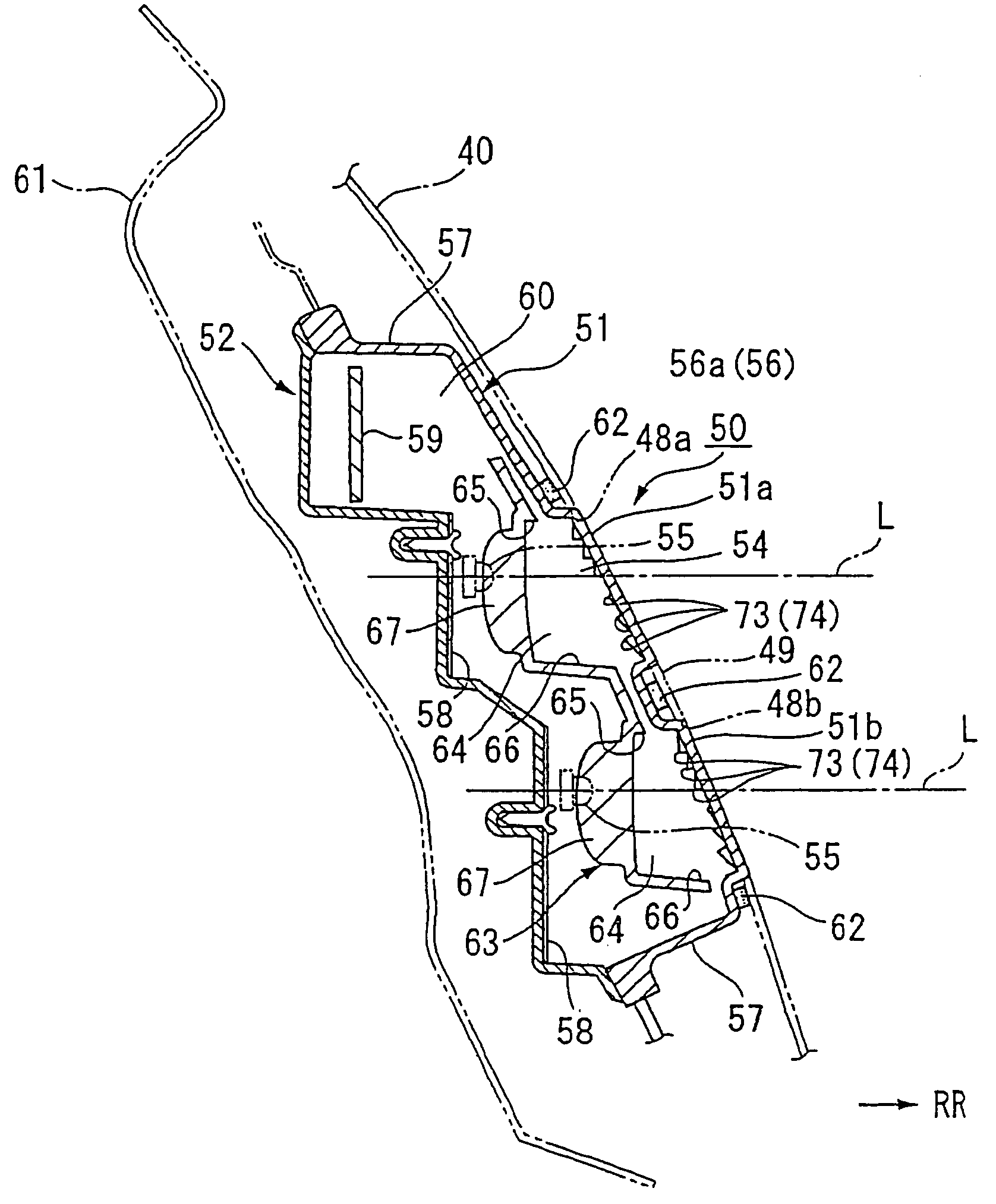
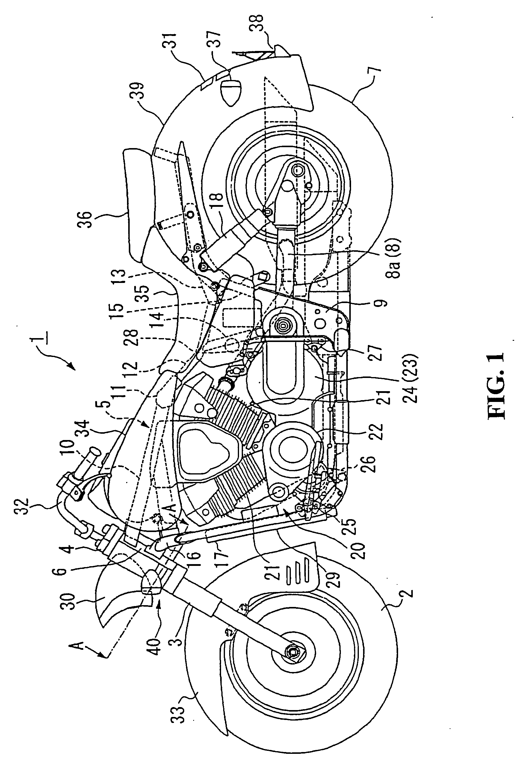
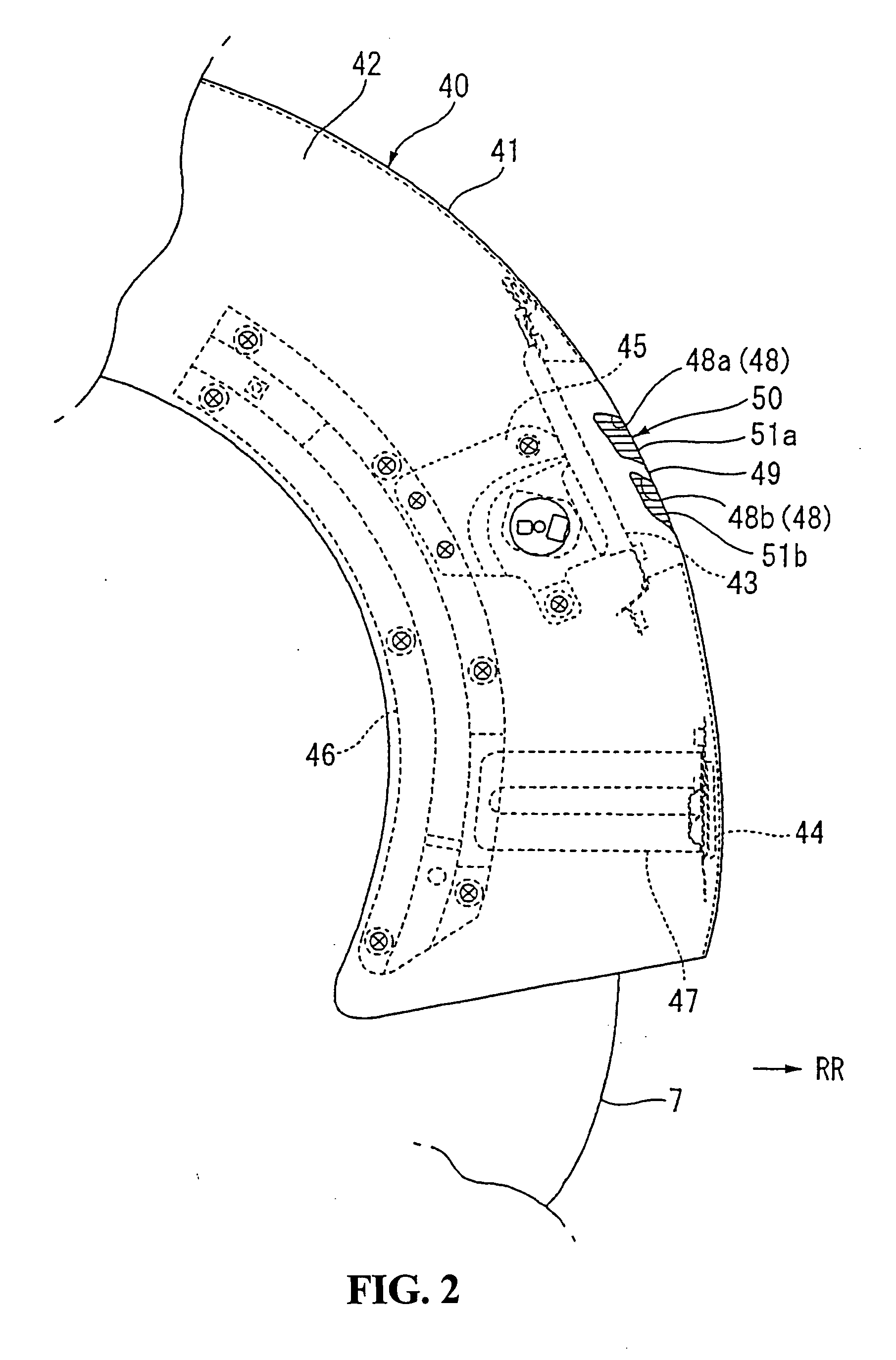
[0033] Referring now to the drawings, an embodiment of the present invention will be described. Indication of directions such as front, rear, left, and right in description below is the same as the direction based on the direction of the vehicle, and an arrow RR in the drawing indicates the rear of the vehicle.

[0034] As shown in FIG. 1, the left and right pair of front forks 3 rotatably support a front wheel 2 of a motorcycle 1 and are steerably supported by a head pipe 6 of a vehicle body frame 5 via a steering stem 4 at the upper end thereof. Rear swing arm portions 8 for rotatably supporting a rear wheel 7 are swingably supported by pivot plates 9 provided at the rear portion of the vehicle body frame 5 at the front ends thereof.

[0035] The vehicle body frame 5 includes a main pipe 10 extending from the upper portion of the head pipe 6 rearwardly. An upper pipe joint 11 is joined to the rear portion of the main pipe 10. A pair of left and right center upper pipes 12 branch towar...


PUM


Abstract

To provide a rear lamp unit for a vehicle which is provided with a desired cut pattern on an outer lens so that the light-emitting area can be increased. A rear lamp unit is provided with upper and lower outer lenses for guiding light emitted from light-emitting diodes to the outside the vehicle. The upper and lower inner lenses are provided between the light-emitting diodes and the upper and lower outer lenses, respectively, and the upper and lower inner lenses are disposed at locations apart from the upper and lower outer lenses, respectively.

Description

CROSS-REFERENCE TO RELATED APPLICATIONS [0001] The present application is related to Japanese Patent Application No. 2003-312915 filed on Sep. 4, 2003 the entire contents of which are hereby incorporated by reference. BACKGROUND OF THE INVENTION [0002] 1. Field of the Invention [0003] The present invention relates to a rear lamp unit for a vehicle such as a motorcycle. [0004] 2. Description of Background Art [0005] A rear lamp unit for a vehicle such as a motorcycle includes a tail lamp which is illuminated for identifying the presence of the vehicle to the rear, and a brake lamp which is illuminated for notifying that the vehicle is in a braking action, and so on. In the rear lamp units, a plurality of light-emitting diodes (so-called LED) are used as a light source. For example, see JP-A-2003-54460. In such a rear lamp unit, a flexibility in the design of the rear lamp unit and the rear portion of the vehicle body is such that the shape of the lens which is large in ratio can be s...

Claims


Application Information

Patent Timeline
Patent Type & Authority Applications(United States)
IPC IPC(8): F21S8/10B60Q1/26B60Q1/44F21V5/00F21V5/04F21W101/14F21Y101/02
CPCB60Q1/2607B60Q1/2696F21S48/2212F21S48/215B62J6/04B62J6/045F21S43/14F21S43/26
Inventor NAKAYAMA, MASARUOSUGI, HIROYUKIKANAOKA, YOJIMAEDA, SHINICHIMIYAGAWA, TORU
Owner HONDA MOTOR CO LTD
Why Eureka
Try Eureka