Light-emitting apparatus and structure for attaching light-emitting apparatus to heat sink

a technology of light-emitting apparatus and heat sink, which is applied in the direction of lighting and heating apparatus, semiconductor devices for light sources, lighting support devices, etc., can solve the problems of decreased mounting area of led chips in printed circuit boards, increased size of illuminating parts of apparatus inclusive of heat sinks, and increased size of led chips in the heat sinks. , to achieve the effect of reducing the attachment area, increasing the light emission area and reducing the siz

Inactive Publication Date: 2015-10-01
SHARP KK
View PDF5 Cites 18 Cited by
  • Summary
  • Abstract
  • Description
  • Claims
  • Application Information

AI Technical Summary

Benefits of technology

[0084]As is apparent from the above, the light-emitting apparatus according to an aspect of the present invention includes a heat-sink attachment part having a heat-sink attachment male thread on a side surface of the substrate, on which substrate a plurality of LED chips are mounted. Therefore, the light-emitting apparatus may be attached to the heat sink by engaging the male thread of the heat-sink attachment part with a female thread formed an inner surface of the light-emitting apparatus attachment hole provided in the heat sink. In this case, there is nothing that interferes with the light-emitting part of the light-emitting apparatus.
[0085]Thus, if the attachment area of the substrate to the heat sink is made equal in size to the conventional substrate, the light-emitting part may be set larger in size than the conventional light-emitting part. On the other hand, if the light-emitting part is made equal in size to the conventional light-emitting part, the attachment area of the substrate may be set smaller in size than the conventional substrate. Thus, the attachment area may be decreased or the light emission area may be increased.
[0086]In the light-emitting apparatus according to another aspect of the present invention, a heat-sink attachment hole, which is formed of a hole with a female thread formed in its inner surface, is provided in proximity to the light-emitting part in the substrate. And, the head of a heat-sink attachment screw, which is to be engaged with the female thread of the heat-sink attachment hole, and the light-emitting part overlap with each other as viewed in the axial direction of the heat-sink attachment hole. That is, the heat-sink attachment hole is provided in close proximity to the light-emitting part.
[0087]Thus, if the attachment area of the substrate to the heat sink is made equal in size to the conventional substrate, the light-emitting part may be set larger in size than the conventional light-emitting part. On the other hand, if the light-emitting part is made equal in size to the conventional light-emitting part, the attachment area of the substrate may be set smaller in size than the conventional substrate. Thus, the attachment area may be decreased or the light emission area may be increased.
[0088]In the structure for attaching a light-emitting apparatus to a heat sink according to a further aspect of the invention, for tightening of a substrate (which has a light-emitting part mounted with a plurality of LED chips) and a heat sink with a screw, the screw is inserted through the through hole in the heat sink toward the hole of the substrate. Therefore, the head of the screw is allowed to extend beyond the substrate area as viewed in a plan view without the possibility of coming into contact with the light-emitting part. For this reason, the hole to be formed in the substrate may be formed in a peripheral portion of the substrate. In this case, the hole may be formed in close proximity to the light-emitting part.
[0089]That is, the substrate does not require any protruding portions or angle members to be used for attachment to the heat sink. Therefore, if the attachment area of the substrate to the heat sink is made equal in size to the conventional substrate, the light-emitting part may be set larger in size than the conventional light-emitting part. On the other hand, if the light-emitting part is made equal in size to the conventional light-emitting part, the attachment area of the substrate may be set smaller in size than the conventional substrate. Thus, the attachment area may be decreased or the light emission area may be increased.

Problems solved by technology

As a consequence, the zirconia-containing alumina substrate has an increased attachment area by a protruding extent of the protruding portions relative to its size proper, so that an illuminating part inclusive of the heat sink also has an increased size accordingly, which is a problem.
Therefore, as in the case of the conventional light-emitting device mounting substrate, the illuminating apparatus has an increased attachment area to the heat sink by a protruding extent of the bent end portions screwed to the heat sink, so that an illuminating part of the apparatus inclusive of the heat sink also has an increased size accordingly, which is a problem.
Furthermore, since the printed circuit board is pressed against the heat sink by the other bent end portion of the angle member, a mounting area for the LED chips in the printed circuit board is decreased by an extent corresponding to the bent end portion, leading to a problem of a decreased light emission area.

Method used


Image

  • Light-emitting apparatus and structure for attaching light-emitting apparatus to heat sink
  • Light-emitting apparatus and structure for attaching light-emitting apparatus to heat sink
  • Light-emitting apparatus and structure for attaching light-emitting apparatus to heat sink

Examples


first embodiment

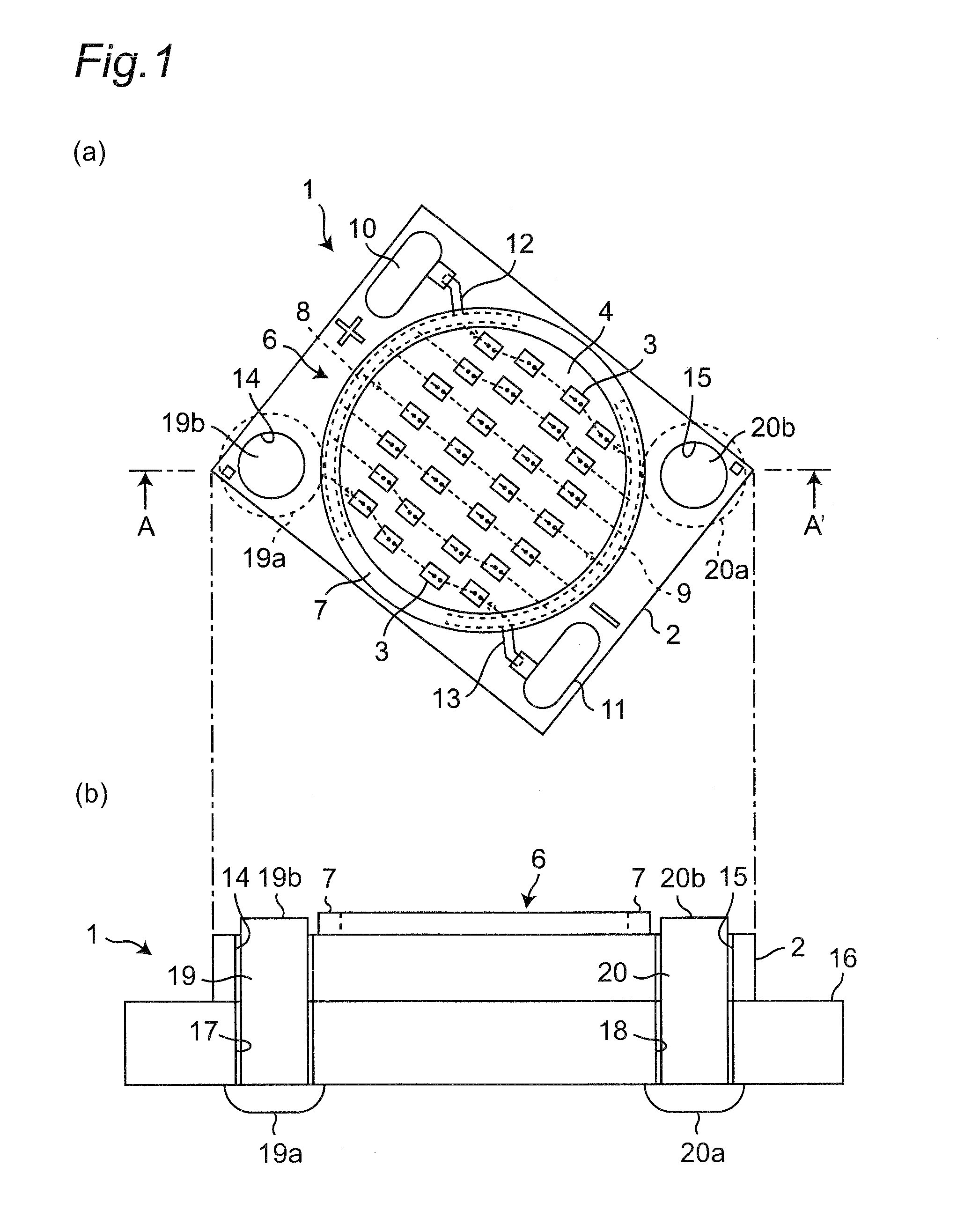
[0108]FIG. 1 is a view showing a structure for attaching a light-emitting apparatus to a heat sink according to this embodiment, wherein FIG. 1(a) is a top view and FIG. 1(b) is a sectional view taken along the line A-A′ of FIG. 1(a).

[0109]As shown in FIG. 1(a), a light-emitting apparatus 1 has a rectangular ceramic substrate 2 and a light-emitting part 6 formed on the rectangular ceramic substrate 2, the light-emitting part 6 having a plurality of LED chips 3 mounted on the substrate 2 and sealed with a transparent fluophor-containing resin 4.

[0110]Around the LED chips 3 on the ceramic substrate 2, circular arc-shaped anode-side wiring pattern 8 and cathode-side wiring pattern 9 are formed in opposition to each other so as to surround the plurality of LED chips 3. In this case, the anode-side wiring pattern 8 and the cathode-side wiring pattern 9 are placed so as to form part of an annular ring as viewed in a plan view.

[0111]An anode-electrode land portion 10 is formed at one of tw...

second embodiment

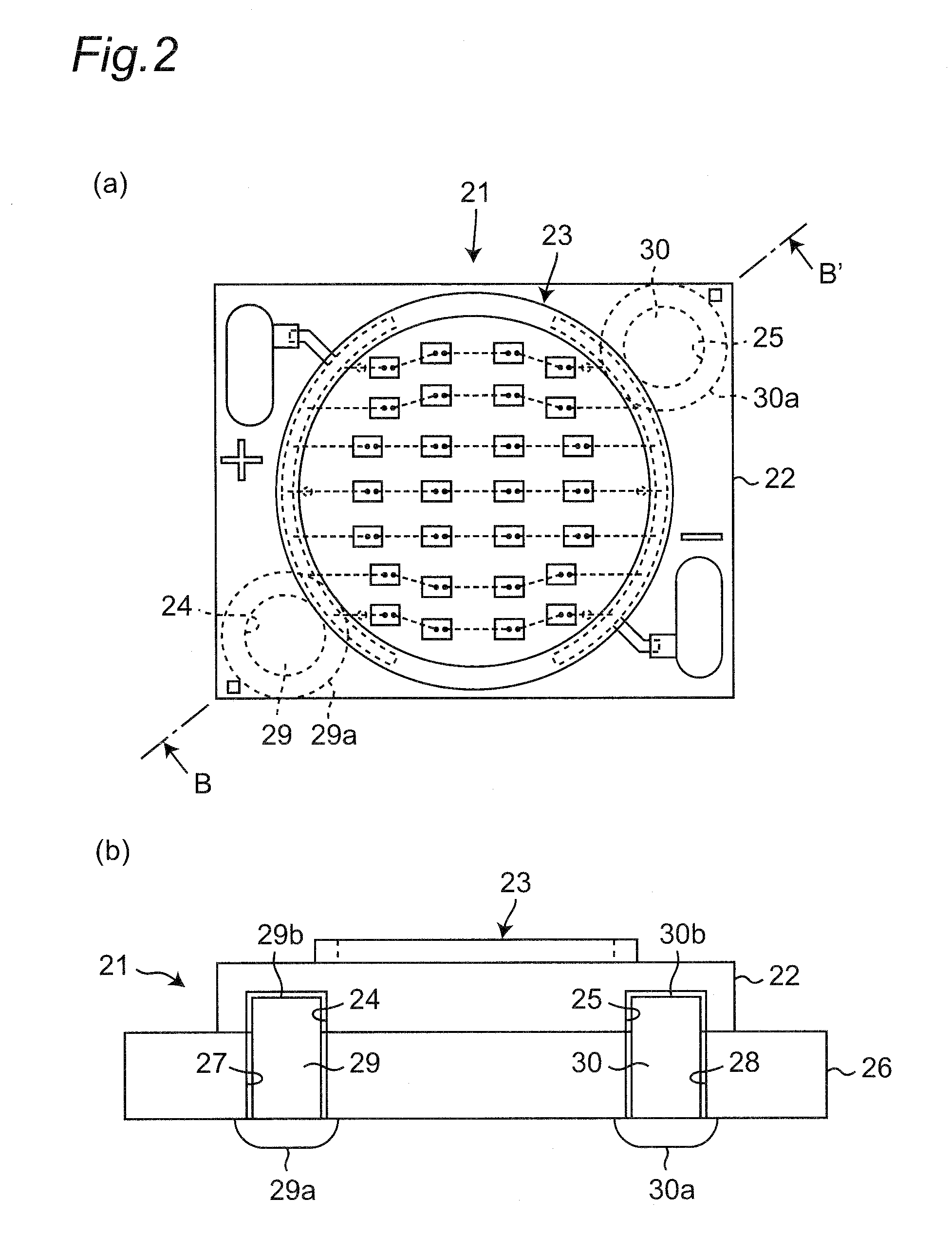
[0125]FIG. 2 is a view showing an attachment structure different of the light-emitting apparatus to the heat sink according to this embodiment, wherein FIG. 2(a) is a top view and FIG. 2(b) is a sectional view taken along the line B-B′ of FIG. 2(a).

[0126]As shown in FIG. 2(a), a light-emitting apparatus 21 is so constructed that a light-emitting part 23 identical in construction to the light-emitting part 6 of the first embodiment is formed on a rectangular ceramic substrate 22.

[0127]As shown in FIG. 2(a) and FIG. 2(b), the ceramic substrate 22 has a bottomed hole 24 having an opening on a heat sink 26 side thereof. The bottomed hole 24 is bored at one of two corner portions positioned on a diagonal line of the ceramic substrate 22 where no land portions for anode electrode and cathode electrode are formed. Also, another bottomed hole 25 having an opening on the heat sink 26 side is bored at the other corner portion of the ceramic substrate 22. Also, in the heat sink 26, through hol...

third embodiment

[0146]FIG. 4 is a view showing an attachment structure of a light-emitting apparatus to a heat sink according to this embodiment, in which FIG. 4(a) is a top view and FIG. 4(b) is a sectional view taken along the line D-D′ of FIG. 4(a).

[0147]As shown in FIG. 4(a), a light-emitting apparatus 51 has a rectangular ceramic substrate 52 and a light-emitting part 56 formed on the rectangular ceramic substrate 52, the light-emitting part 56 having a plurality of LED chips 53 mounted on the ceramic substrate 52 and sealed with a transparent fluophor-containing resin 54.

[0148]Around the LED chips 53 on the ceramic substrate 52, a circular arc-shaped anode-side wiring pattern 58 and a circular arc-shaped cathode-side wiring pattern 59 are formed in opposition to each other so as to surround the plurality of LED chips 53. In this case, the anode-side wiring pattern 58 and the cathode-side wiring pattern 59 are placed so as to form part of an annular ring as viewed in a plan view. Further, in c...


PUM


Abstract

A light-emitting apparatus has a substrate (72) having a generally disc shape, a light-emitting part (76) having a plurality of LED chips (73) mounted on one main surface of the substrate (72), the plurality of LED chips (73) being sealed with a resin (74), and a heat-sink attachment part having a heat-sink attachment male thread (80) formed on a side surface of the substrate (72). When the attachment area of the substrate (72) to the heat sink is kept the same, the light-emitting part (76) may be enlarged, and when the light-emitting unit (76) is kept the same, the attachment area of the substrate (72) may be reduced.

Description

TECHNICAL FIELD[0001]The present invention relates to COB (Chip on Board) type light-emitting apparatuses and structures for attaching a COB type light-emitting apparatus to a heat sink.BACKGROUND ART[0002]Conventional methods for attaching a COB type light-emitting apparatus to a heat sink are known from JP 2012-4400 A (PTL1) disclosing a light-emitting device mounting substrate and also from JP 2010-251192 A (PTL2) disclosing an illuminating apparatus.[0003]With regard to the light-emitting device mounting substrate, a plurality of divided copper sheet pieces are joined directly to one main surface of a rectangular plate-shaped zirconia-containing alumina substrate while an undivided copper sheet is joined directly to the other main surface. A plated coating is provided on surfaces of the divided copper sheet pieces and the surface of the undivided copper sheet. Then, mutually opposing side edges of the undivided copper sheet are provided with protruding portions protruding theref...

Claims


Application Information

Patent Timeline
Patent Type & Authority Applications(United States)
IPC IPC(8): F21V29/70H01L33/54H01L33/62H01L33/64F21V23/00H01L25/075
CPCF21V29/70F21V23/005H01L25/0753F21Y2101/02H01L33/644H01L33/54H01L33/62H05K1/0209H01L33/64H01L2224/48137H01L2224/48091H05K3/0061H05K2201/066H05K2201/10106H01L2924/00014F21Y2115/10
Inventor HATA, TOSHIOAGATANI, MAKOTONADA, TOMOKAZUFUJITA, YUHSUKEYAMAGUCHI, IPPEIKONISHI, MASAHIRO
Owner SHARP KK
Why Eureka
Try Eureka