Efficient condensation heat exchanger of heating system

A technology of condensing heat exchangers and heating systems, which is applied in the direction of air heaters, fluid heaters, lighting and heating equipment, etc. It can solve the problems of inconvenient discharge of condensed water, improve energy utilization, reduce separate discharge, reduce The effect of emissions

Inactive Publication Date: 2021-03-09
WUXI XIZHOU MACHINERY
View PDF3 Cites 0 Cited by
  • Summary
  • Abstract
  • Description
  • Claims
  • Application Information

AI Technical Summary

Problems solved by technology

[0003] Therefore, the technical problem to be solved by the present invention is to overcome the defects of inconvenient discharge of condensed water due to the large opening and the influence of surface tension in the condensed water discharge process in the prior art, thereby providing a high-efficiency condensing heat exchanger for heating system

Method used


Image

  • Efficient condensation heat exchanger of heating system

Examples


Embodiment Construction

[0014] In order to make the object, technical solution and advantages of the present invention clearer, the present invention will be further described in detail below in conjunction with the accompanying drawings and embodiments. It should be understood that the specific embodiments described here are only used to explain the present invention, not to limit the present invention.

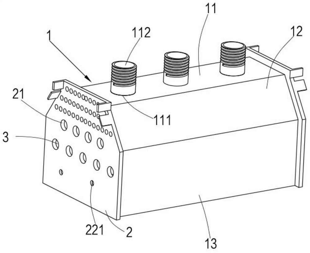
[0015] see figure 1 , a high-efficiency condensing heat exchanger for a heating system, comprising a shell 1, a tube sheet 2, and heat exchange tubes 3, the tube sheets 2 are arranged at both ends of the shell 1 in the longitudinal direction and fixed on the shell 1 on. In one embodiment, the tube plate 2 is welded and fixed on the shell 1 , and in other embodiments, the tube plate 2 can also be fixed on the shell 1 by bolts. The heat exchange tubes 3 are located in the housing 1 , and both ends of the heat exchange tubes 3 are arranged through the tube sheets 2 at both ends.

[0016] In one emb...


PUM


Abstract

The invention relates to the technical field of heat exchanger equipment, in particular to an efficient condensation heat exchanger of a heating system, and aims at solving the problem that in the prior art, waste gas is directly exhausted from a top opening, and consequently the surrounding environment is prone to being affected. The heat exchanger is technically characterized by comprising a shell, tube plates and heat exchange tubes, wherein the tube plates are arranged at the two ends of the shell in the length direction and are fixed to the shell, the shell comprises a top plate and an extension plate, the extension plate is perpendicular to the top plate, exhaust ports are formed in the shell and penetrate through the shell, an extension tube is arranged at each exhaust port in an upward extending mode, and the extension tubes are fixedly arranged on the exhaust ports. Through the arrangement of the extension tubes and the exhaust ports, the attachment area of a single exhaust port is reduced, condensate water can form water drops more easily, more toxic substances can be adsorbed when the condensate water is discharged and passes through the extension tubes, therefore, separate discharging of the toxic substances is reduced, and environmental pollution is relieved.

Description

technical field [0001] The invention relates to the technical field of heat exchanger equipment, in particular to a high-efficiency condensing heat exchanger for a heating system. Background technique [0002] Condensing heat exchangers usually install heat exchange tubes inside the shell, and pass high-temperature flue gas through the heat exchange tubes to exchange heat for the heat exchange liquid in the heat exchange tubes. During the heat exchange process, the water vapor inside the shell will change due to temperature Reduce the adhesion on the outer wall of the heat exchange tube and the inner wall of the shell. The traditional condensing heat exchanger discharges the condensed water through the opening at the top plate. Due to the large opening, the condensed water forms water droplets due to surface tension and adheres to the opening of the shell. , increasing the difficulty of emission. Contents of the invention [0003] Therefore, the technical problem to be so...

Claims


Application Information

Patent Timeline
Patent Type & Authority Applications(China)
IPC IPC(8): F24H8/00F24H9/00
CPCF24H8/00F24H9/0005Y02B30/00
Inventor 包建忠司存信王正阳
Owner WUXI XIZHOU MACHINERY
Why Eureka
Try Eureka