Temporary substrate, transfer method and production method

a technology of transfer method and production method, applied in the field of temporary substrates, can solve the problems of increasing increasing the time required for detachment, and being very slow to process, so as to reduce the risk of premature detachment, shorten the time necessary for detachment, and gain processing time

Active Publication Date: 2016-03-01
SOITEC SA
View PDF11 Cites 0 Cited by
  • Summary
  • Abstract
  • Description
  • Claims
  • Application Information

AI Technical Summary

Benefits of technology

[0011]The present disclosure advantageously provides a temporary substrate facilitating final detachment, while eliminating the risk of premature detachment. This temporary substrate makes it possible to gain processing time by shortening the time necessary for detachment. This temporary substrate does not comprise adhesive material that would degrade if exposed to the required thermal treatment, and thus can sustain temperatures greater than 200° C.
[0014]The presence of these inserts with a different coefficient of thermal expansion means that by heating the structure before detachment, cavities appear at the interface between the temporary substrate substrate, according to the disclosure, and the original substrate. The area of attachment is thus reduced, which, in turn, brings about a considerable reduction in the overall adhesion and easy detachment of the thin layer.

Problems solved by technology

However, a physical limit is being approached.
One difficulty lies in the final detachment of the temporary substrate 100.
These solutions give satisfaction but remain very slow to process: the larger the substrate, the longer the detachment time.
Although for 100 mm diameter substrates the detachment time may be acceptable, this detachment time proves to be much too long for profitable industrial use for substrates having diameters of 200 mm, 300 mm, or more.
European patent application EP 1889887 discloses a temporary substrate with an adhesive layer incorporating thermally expandable microspheres, but the temporary substrate described in this document cannot be used for a processing step that requires a temperature greater than 140° C. Additionally, the nature of the adhesive layer and the uncontrolled disposition of the microspheres into the adhesive layer does not meet the requirements of providing a sufficiently high adhesion during processing and enabling the controlled detachment of the substrate after processing.

Method used


Image

  • Temporary substrate, transfer method and production method
  • Temporary substrate, transfer method and production method
  • Temporary substrate, transfer method and production method

Examples


Embodiment Construction

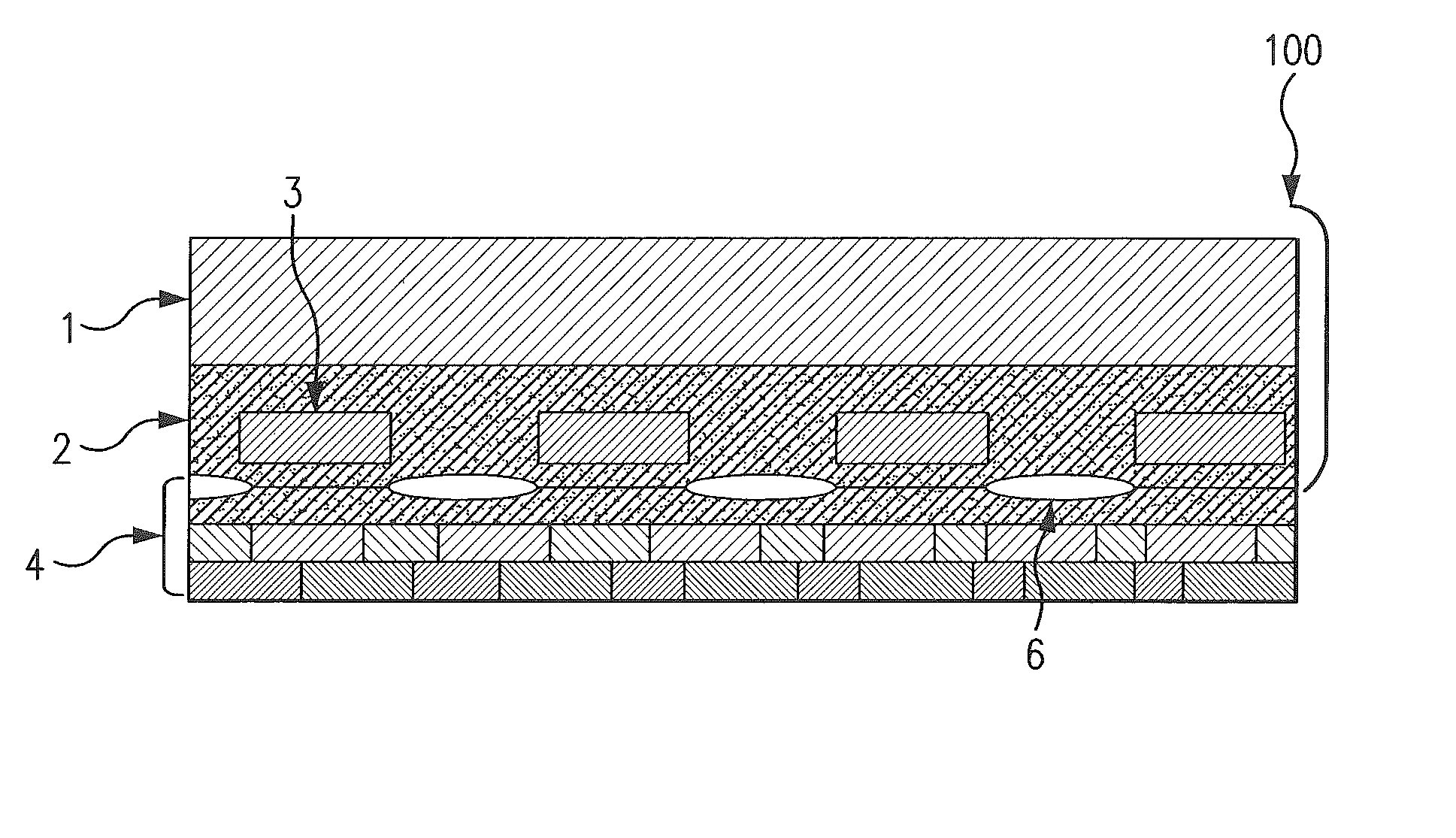
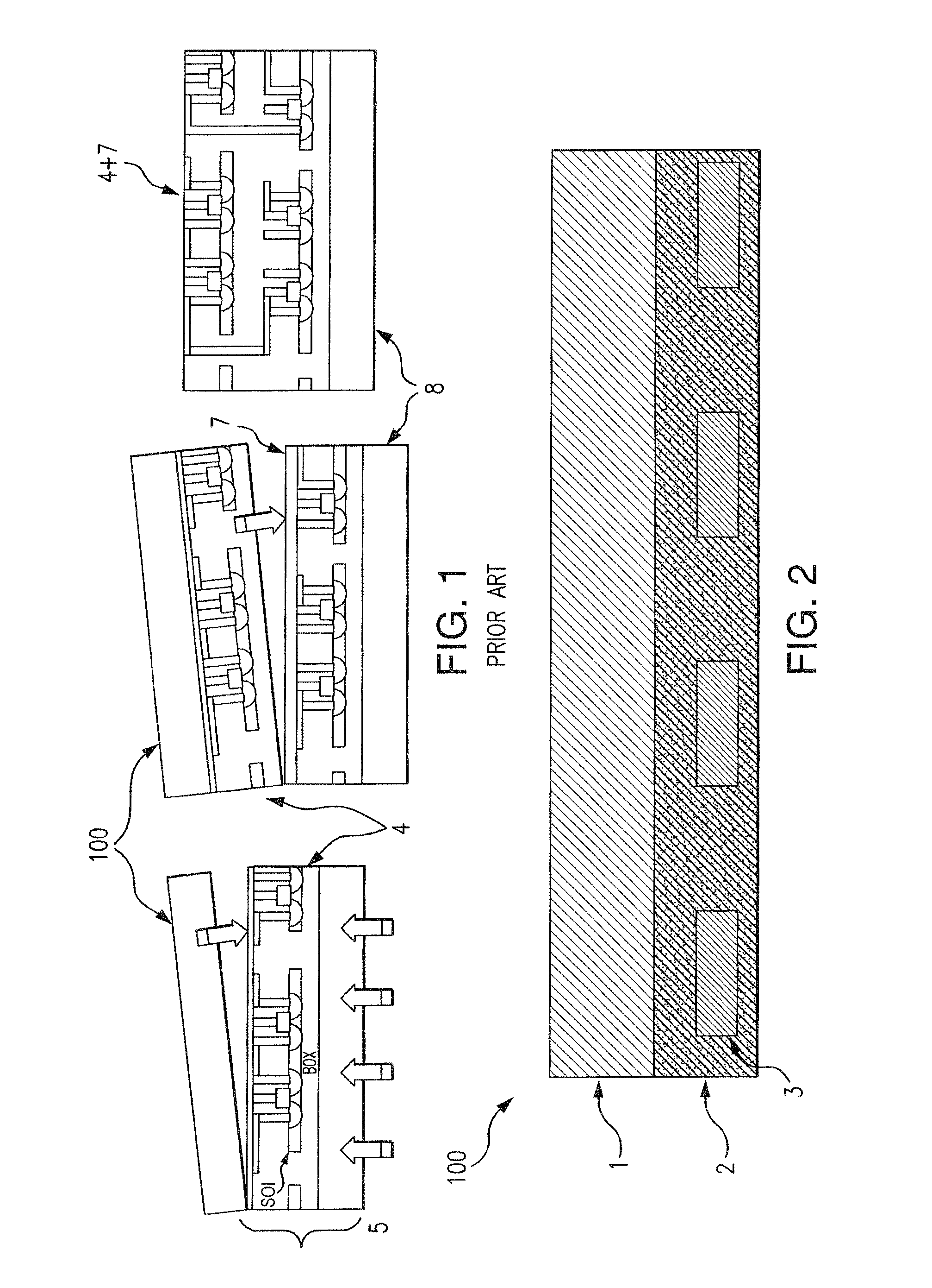
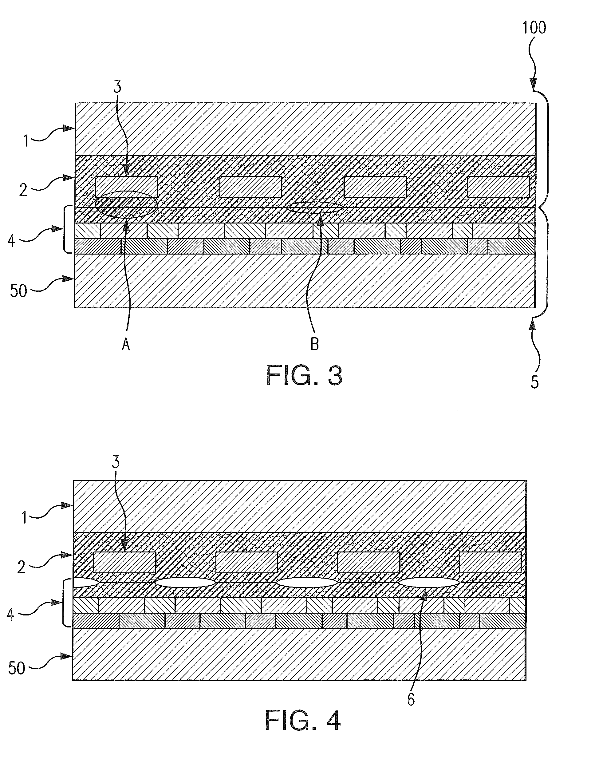
[0052]In a preferred embodiment, the disclosure includes a temporary substrate having a bonding surface prepared for receiving an additional substrate that will transfer a thin layer. This temporary substrate comprises a principal part or support and a surface layer thereon with the surface layer having a plurality of inserts therein. These inserts are preferably made of a material having a coefficient of thermal expansion that is significantly different from that of the material constituting the surface layer.

[0053]Another preferred embodiment relates to a method for transferring a thin layer onto a temporary substrate. This method comprises preparing a bonding surface on a temporary substrate of the type described herein; bonding an original substrate to the temporary substrate at a bonding interface; removing part of the original substrate to provide a selected portion of the original substrate on the surface layer; heat treating the bonded substrates to form detachment zones but...


PUM

PropertyMeasurementUnit
surface roughnessaaaaaaaaaa
widthaaaaaaaaaa
widthaaaaaaaaaa

Abstract

Temporary substrates may include a bonding surface prepared for receiving an additional substrate that will transfer a thin layer. Such substrates may include a principal part or support and a surface layer thereon with the surface layer having a plurality of inserts therein. The inserts are made of a material having a coefficient of thermal expansion that is significantly different from that of the material constituting the surface layer. Processing methods for transferring a selected portion of an original substrate may involve such temporary substrates and productions methods may produce such temporary substrates.

Description

CROSS-REFERENCE TO RELATED APPLICATION[0001]This application is a continuation-in-part of U.S. patent application Ser. No. 12 / 897,409, filed Oct. 4, 2010, the entire content of which is expressly incorporated herein by reference thereto. This application claims priority to French Patent Application Serial No. FR1055767, filed Jul. 15, 2010.TECHNICAL FIELD[0002]The present disclosure relates to the field of temporary substrates used in the semiconductor industry.BACKGROUND[0003]Semiconducting structures serve as the basis for the electronics industry. In order to improve performance, methods have been developed for more and more increasing the density of circuits per unit area. However, a physical limit is being approached. It is for this reason that three-dimensional integration methods have appeared. Instead of always reducing the size of circuits, it is sufficient to stack them in 3D structures and to connect them by vertical interconnections.[0004]The production of these types of...

Claims


Application Information

Patent Timeline
Patent Type & Authority Patents(United States)
IPC IPC(8): H01L21/30H01L21/46H01L21/683
CPCH01L21/6835H01L2221/6835H01L2221/68318H01L2221/68327H01L2221/68368H01L2221/68381Y10T428/24942
Inventor RIOU, GREGORY
Owner SOITEC SA
Why Eureka
Try Eureka