Magneto-optical recording/reproducing apparatus and magneto-optical recording/reproducing method

a technology of optical recording and magneto-optical recording, which is applied in the field of magneto-optical recording/reproducing apparatus and magneto-optical recording/reproducing method, can solve the problems of loss of magnetization of the recording surface, increase of jitter in the reproduced signal, etc., and achieve the effect of high density data recording

Inactive Publication Date: 2005-03-31
FUJITSU LTD
View PDF2 Cites 0 Cited by
  • Summary
  • Abstract
  • Description
  • Claims
  • Application Information

AI Technical Summary

Benefits of technology

[0021] According to an aspect of the present invention, an edge position of a reproduced mark may not be varied, and thereby, high density data recording may be realized.

Problems solved by technology

Thereby, in a case of reproducing a recorded signal having a high frequency, increased jitters in the reproduced signal may be a problem.
According to the magnetic field modulation method, when a laser beam is irradiated on a recording surface, the temperature of the recording surface rises, and when this temperature rises above the Curie point, the magnetization of the recording surface is lost.

Method used


Image

  • Magneto-optical recording/reproducing apparatus and magneto-optical recording/reproducing method
  • Magneto-optical recording/reproducing apparatus and magneto-optical recording/reproducing method
  • Magneto-optical recording/reproducing apparatus and magneto-optical recording/reproducing method

Examples


second embodiment

[0049] In the following, the present invention is described with reference to FIGS. 3 and 4.

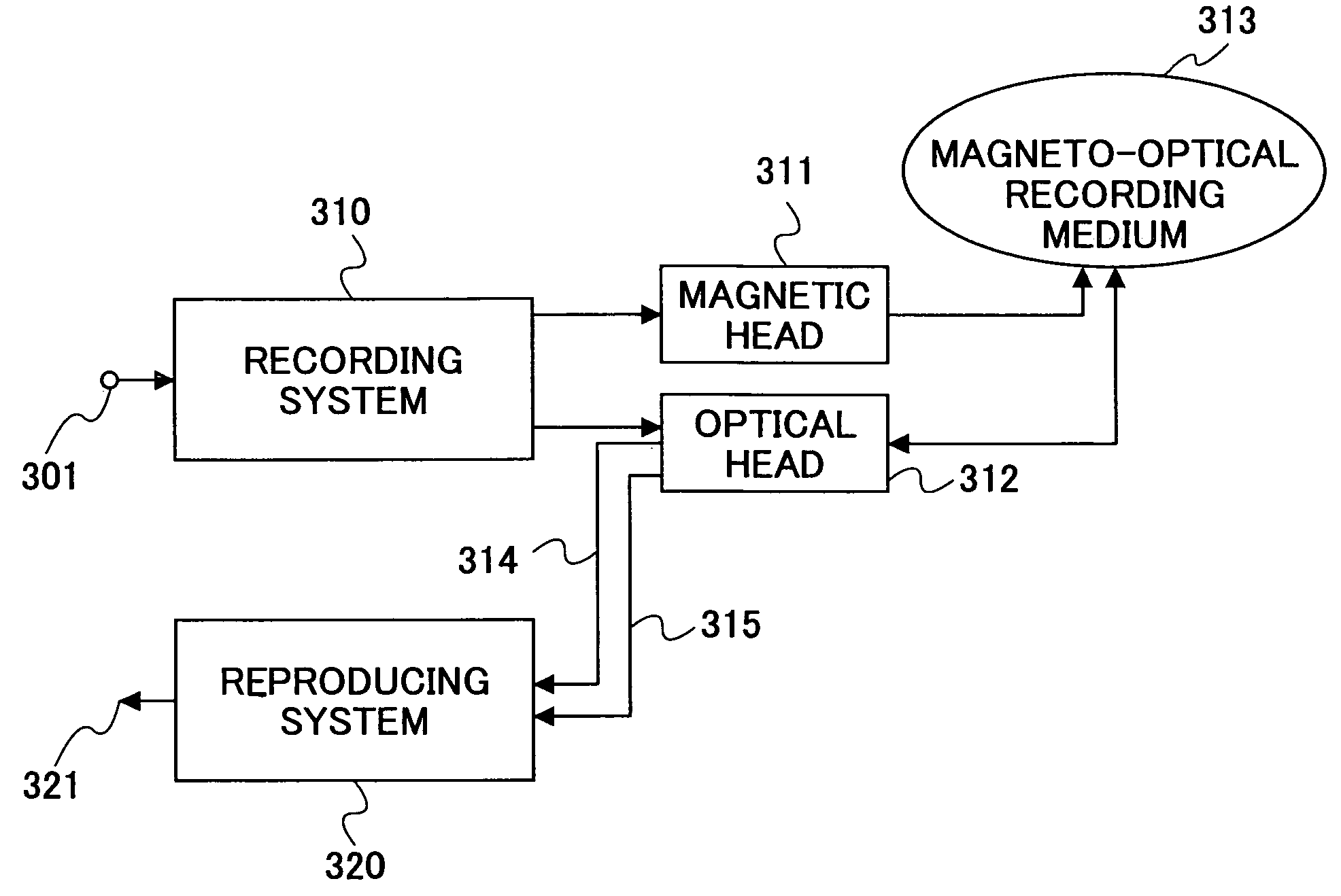
[0050]FIG. 3 is a block diagram showing a configuration of a high-density magneto-optical recording / reproducing apparatus according to an embodiment of the present invention. The high-density magneto-optical recording / reproducing apparatus of FIG. 3 includes a recording system 310, a magnetic head 311, an optical head 312, and a reproducing system 320. In a recording operation of the present apparatus according to one embodiment, user data 301 to be recorded are input to the recording system 310. In turn, the recording system 310 processes the input user data 301 into a recording signal and outputs the processed signal to the magnetic head 311 and the optical head 312. The magnetic head 311 and the optical head 312 record the signal processed by the recording system 310. In a reproducing operation according to one embodiment, the optical head 312 reads signals recorded on a disk. An MO signal...

third embodiment

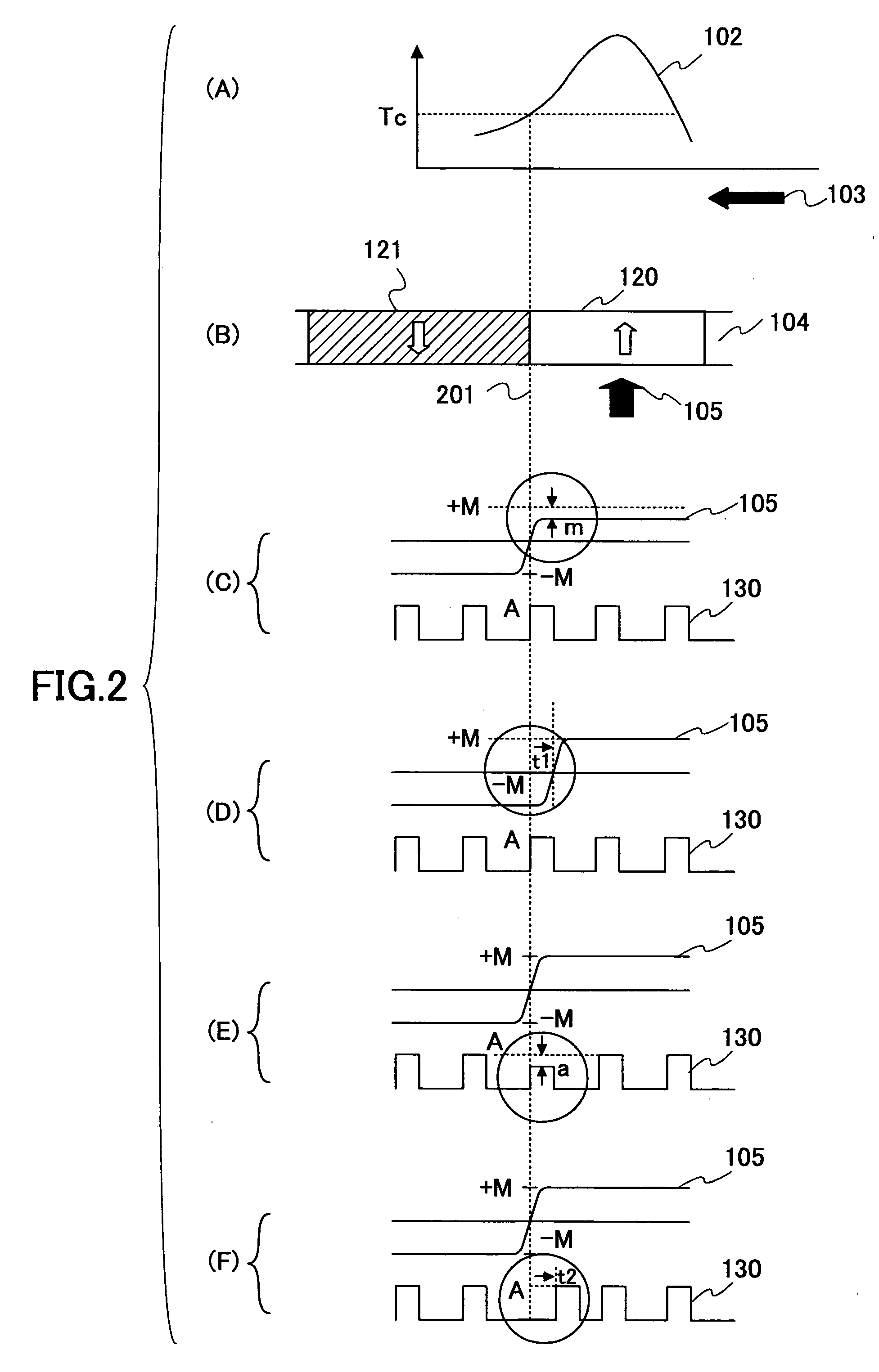
[0056]FIG. 5 is a block diagram showing a configuration of a recording compensation circuit 400 according to the present invention that executes an operation according to the method shown in FIG. 2(C).

[0057] The recording compensation circuit 400 of FIG. 5 includes a mark length detector circuit 402, a magnetic field intensity setting unit 501, a magnetic head drive circuit 404, a laser drive circuit 405, and a clock generating circuit 502. According to the present example, recording data from the modulation circuit 401 of FIG. 4 are supplied to the mark length detector circuit 402 and the magnetic field intensity setting circuit 501. Also, a clock 503 generated by the clock generating circuit 502 is supplied to the magnetic field intensity setting circuit 501 and the laser drive circuit 405. The magnetic field intensity setting circuit 501 and the laser drive circuit 405 operate based on the clock 503 supplied thereto.

[0058] When a long mark having a length that is greater than or...

fourth embodiment

[0060]FIG. 6 shows a configuration of a recording compensation circuit 400 according to the present invention that executes an operation according to the method illustrated by FIG. 2(D).

[0061] The recording compensation circuit 400 of FIG. 6 includes a mark length detector circuit 402, a magnetic field reversal position adjusting unit 601, a magnetic head drive circuit 404, a laser drive circuit 405, and a clock generating circuit 502. According to the present example, recording data 411 from the modulation circuit 401 of FIG. 4 are supplied to the mark length detector circuit 402 and the magnetic field reversal position adjusting unit 601. Also, a clock 503 generated by the clock generating circuit 502 is supplied to the magnetic field reversal position adjusting unit 601 and the laser drive circuit 405. The magnetic field reversal position adjusting unit 601 and the laser drive circuit 405 operate based on the clock 503 supplied thereto.

[0062] When a long mark having a length tha...


PUM

PropertyMeasurementUnit
magnetic fieldaaaaaaaaaa
lengthaaaaaaaaaa
recording magnetic fieldaaaaaaaaaa

Abstract

A magneto-optical recording/reproducing apparatus and a magneto-optical recording/reproducing method are disclosed for preventing a variation of an edge position of a mark reproduced from a recording medium. An exemplary magneto-optical recording/reproducing apparatus for recording/reproducing an information mark on/from a magneto-optical recording medium includes a detection unit for determining the length of a first recording information mark and an adjustment unit for adjusting the intensity of a recording magnetic field for recording a second information mark depending on the length of the first information mark recorded immediately before the second recording information mark.

Description

CROSS REFERENCE TO RELATED APPLICATION [0001] This application is a U.S. continuation application filed under 35 USC 111 (a) claiming benefit under 35 USC 120 and 365 (c) of PCT application JP2002 / 006738 filed on Jul. 3, 2002, which is incorporated herein by reference. BACKGROUND OF THE INVENTION [0002] 1. Field of the Invention [0003] The present invention relates generally to a magneto-optical recording / reproducing apparatus and a magneto-optical recording / reproducing method, and particularly to a magneto-optical recording / reproducing apparatus and a magneto-optical recording / reproducing method that are suitable for recording / reproducing a small mark. [0004] 2. Description of the Related Art [0005] Recording methods for recording information on a magneto-optical disk include an optical modulation method and a magnetic field modulation method. [0006] The optical modulation method involves modulating the irradiation amount of a laser beam according to the information being recorded....

Claims


Application Information

Patent Timeline
Patent Type & Authority Applications(United States)
IPC IPC(8): G11B11/00G11B11/105
CPCG11B11/10506G11B11/10508G11B11/10528G11B20/10037G11B11/10584G11B11/10595G11B20/10009G11B11/1053G11B11/105
Inventor ITAKURA, AKIHIRO
Owner FUJITSU LTD
Why Eureka
Try Eureka