High performance network communication device and method

a network communication and high-performance technology, applied in the field of network communication devices, can solve problems such as data transmission errors, network latency, and network benefits or negative effects of communication across the network

Inactive Publication Date: 2005-03-31
GENERAL ELECTRIC CO
View PDF5 Cites 52 Cited by
  • Summary
  • Abstract
  • Description
  • Claims
  • Application Information

AI Technical Summary

Problems solved by technology

Each of these devices can have beneficial or detrimental effects on the communication across the network.
However, messages received by the network hub can collide in the hub and cause data transmission errors.
However, these switches typically add latency to the network due to the collision management.

Method used


Image

  • High performance network communication device and method
  • High performance network communication device and method
  • High performance network communication device and method

Examples


Embodiment Construction

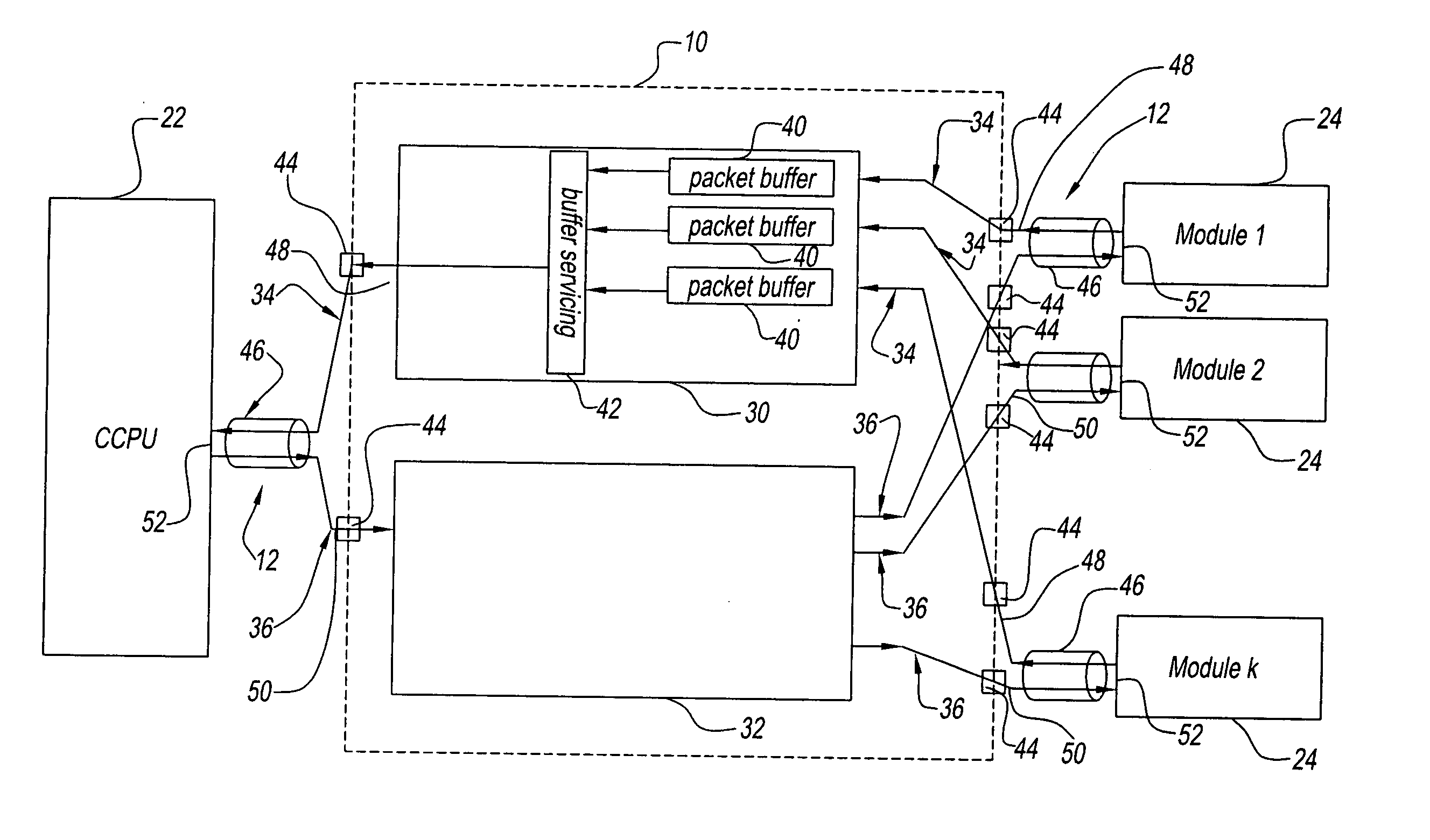
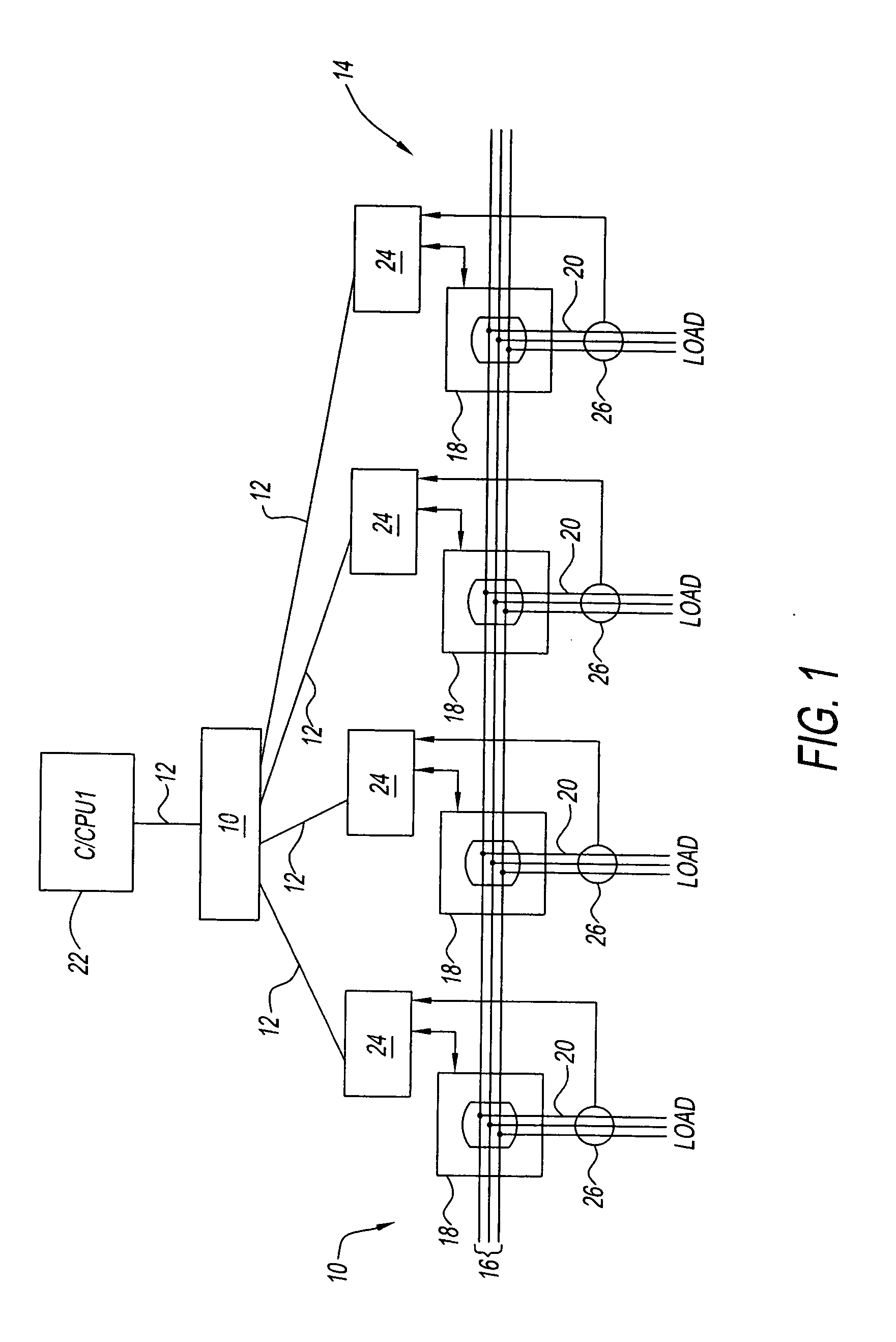
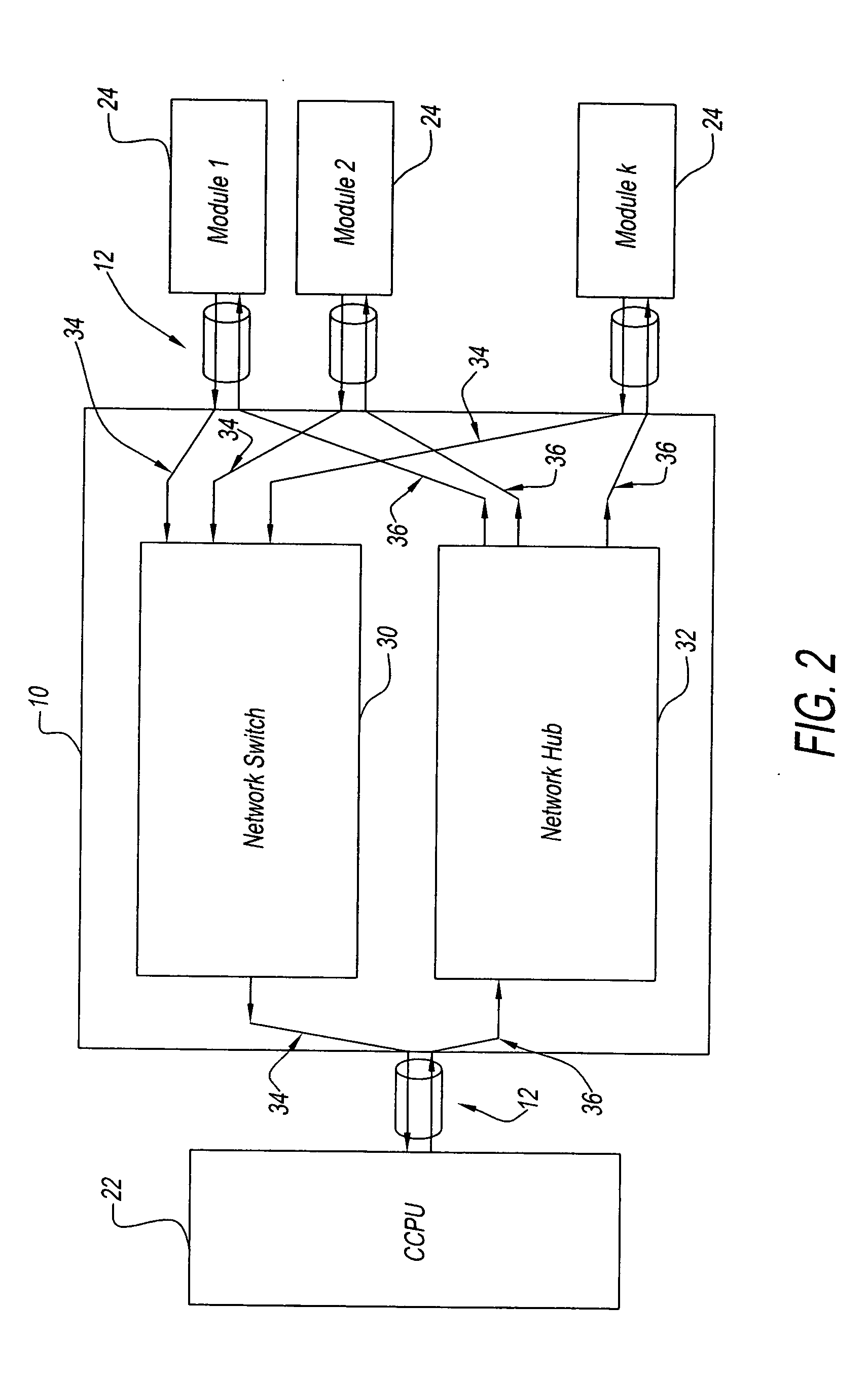
[0013] Referring now to the drawings and in particular to FIG. 1, an exemplary embodiment of a high performance network communication device generally referred to by reference numeral 10 is illustrated. Device 10 is configured to facilitate communication across a data network 12. For example, device 10 and network 12 can be configured to communicate electrical messages, optical messages, acoustic messages, and any combinations thereof.

[0014] For purposes of clarity, device 10 is illustrated in use with a centrally controlled power distribution system 14. System 14 distributes power from at least one power bus 16 through a number or plurality of circuit breakers 18 to branch circuits 20. Each circuit breaker 18 has a set of separable contacts (not shown) that selectively place power bus 16 in electrical communication with at least one load on circuit 20. The load can include devices, such as, but not limited to, motors, welding machinery, computers, heaters, lighting, and / or other e...


PUM


Abstract

A network communication device for bi-directional communication networks is provided having a first portion and a second portion. The first portion is connectable to a first point and a second point on the bi-directional communication network. Similarly, the second portion is connectable to the first and second points. The first portion manages collisions among a first set of messages transmittable from the first point to the second point. However, the second portion transmits free of collision management a second set of messages transmittable from the second point to the first point.

Description

BACKGROUND OF THE INVENTION [0001] The present disclosure relates generally to network communication devices. More particularly, the present disclosure relates to a high performance network communication device and method. [0002] Data networks communicate data among the various points on the network. Such data networks typically require one or more network communication devices, such as network hubs and network switches. Each of these devices can have beneficial or detrimental effects on the communication across the network. [0003] For example, network hubs provide the ability to communicate multiple messages with a minimal latency through the hub. However, messages received by the network hub can collide in the hub and cause data transmission errors. Conversely, network switches manage the collisions created by multiple messages. However, these switches typically add latency to the network due to the collision management. [0004] Accordingly, there is a continuing need for a network...

Claims


Application Information

Patent Timeline
Patent Type & Authority Applications(United States)
IPC IPC(8): H04L12/413
CPCH04L12/40032H04L49/90H04L12/413
Inventor SEXTON, DANIEL WHITEEVANS, SCOTT CHARLESPEARLMAN, MARC ROBERT
Owner GENERAL ELECTRIC CO
Why Eureka
Try Eureka