

Device for delivering viscous material
a technology of viscous material and device, which is applied in the field of medical instruments and methods for delivering viscous material, can solve the problems of high pressure build-up within the device, the clinician is exposed to significant radiation produced by the fluoroscope, and the number of serious health risks, so as to minimize safety concerns and ensure the removal of the clinician
- Summary
- Abstract
- Description
- Claims
- Application Information
AI Technical Summary
Benefits of technology
Problems solved by technology
Method used
Image

Examples
Embodiment Construction
[0046] Certain exemplary embodiments will now be described to provide an overall understanding of the principles of the structure, function, manufacture, and use of the devices and methods disclosed herein. One or more examples of these embodiments are illustrated in the accompanying drawings. Those of ordinary skill in the art will understand that the devices and methods specifically described herein and illustrated in the accompanying drawings are non-limiting exemplary embodiments and that the scope of the present invention is defined solely by the claims. The features illustrated or described in connection with one exemplary embodiment may be combined with the features of other embodiments. Such modifications and variations are intended to be included within the scope of the present invention.
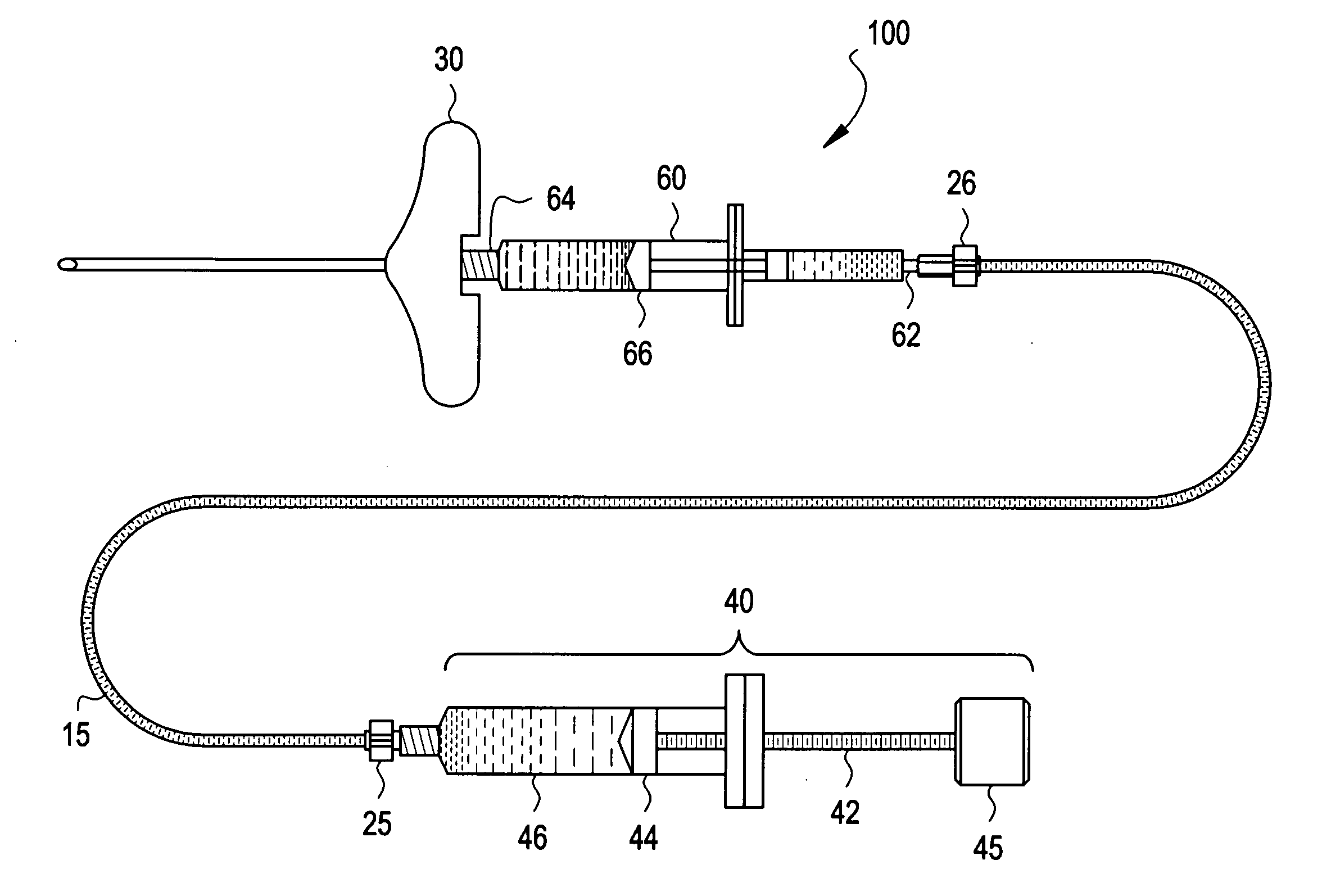
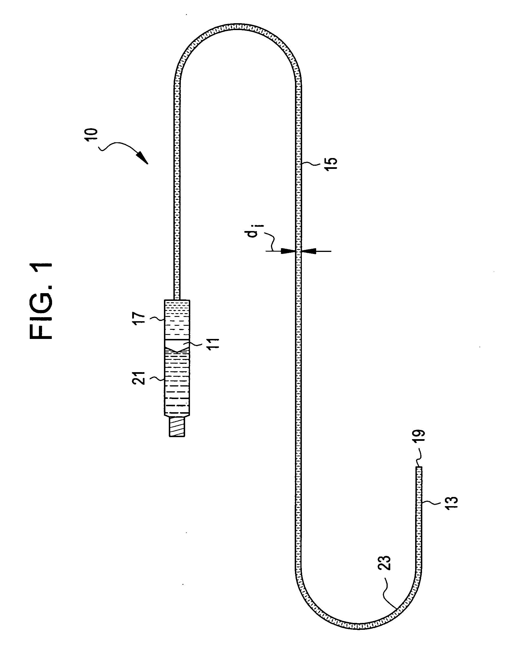
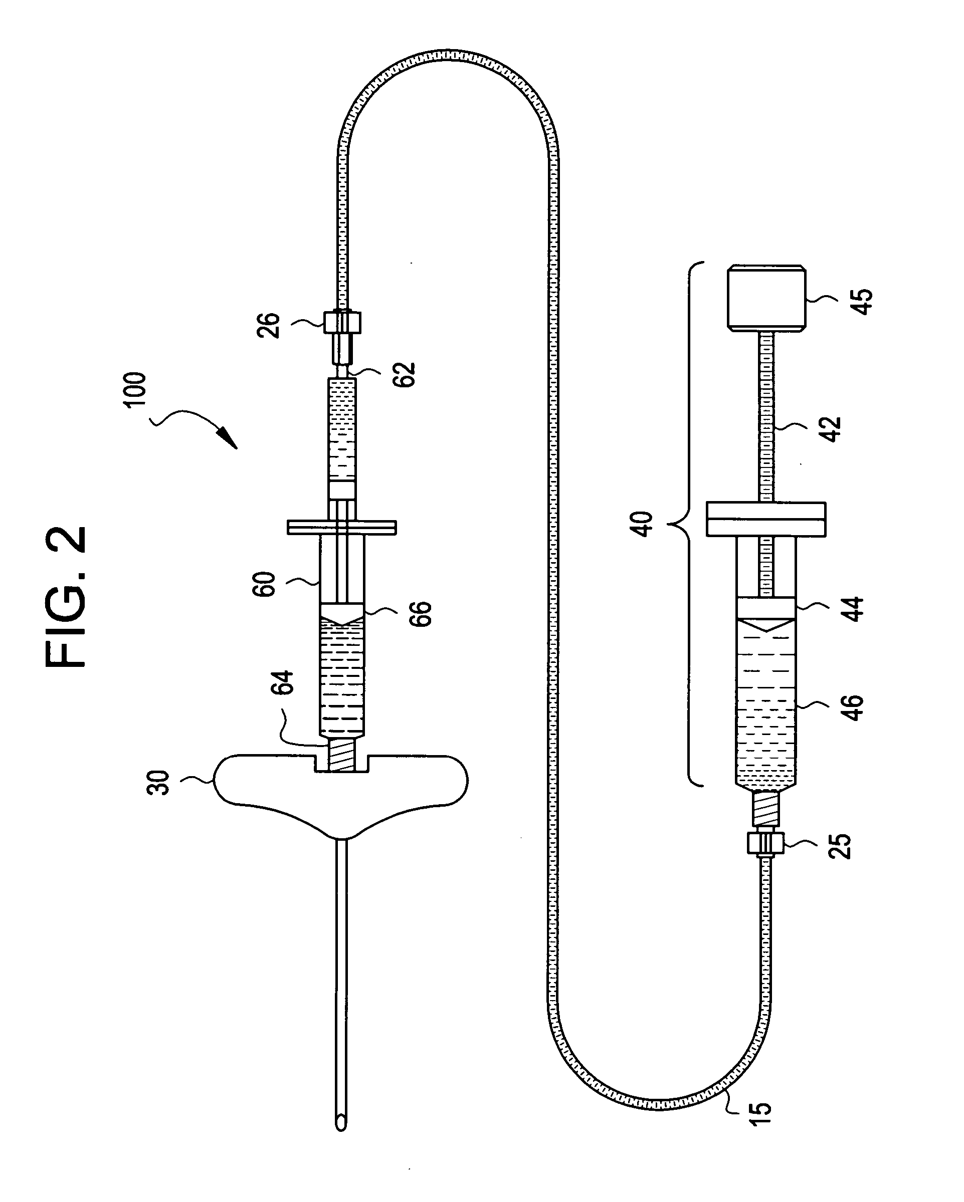
[0047] The present invention is directed to devices and methods for remotely delivering a viscous material to a targeted site in a patient. In general, the device is a delivery tube contai...
PUM
 Abstract
Description
Claims
Application Information