
Variational modeling using extension types

a technology of extension types and variables, applied in the field of software artifact modeling, can solve problems such as frustration for users, software engineering discipline faces similar problems, and simple changes can be frustrating

Inactive Publication Date: 2005-03-31
IBM CORP
View PDF0 Cites 36 Cited by
  • Summary
  • Abstract
  • Description
  • Claims
  • Application Information

AI Technical Summary

Problems solved by technology

A conceptually simple change can be frustrating since one may have to reposition many, if not all, control points to achieve the desired result.
In surface modeling this kind of problem arises whenever controls provided to user are closely tied the representation's degree of freedom, since no fixed set of controls can be expected to anticipate all of the users' needs.
Software engineering discipline faces similar problems.
When modeling software engineering artifacts, a user can often be frustrated because control points provided to the user are closely tied to the representations' degree of freedom.
In that class extensions tend not to represent the only type of controls that a user wants, it is often very difficult, if not impossible, to make a simple change, such as adding logging feature to a set of classes.
However, the current AOSD methodologies are quite far from achieving a complete separation of control from representation.

Method used


Image

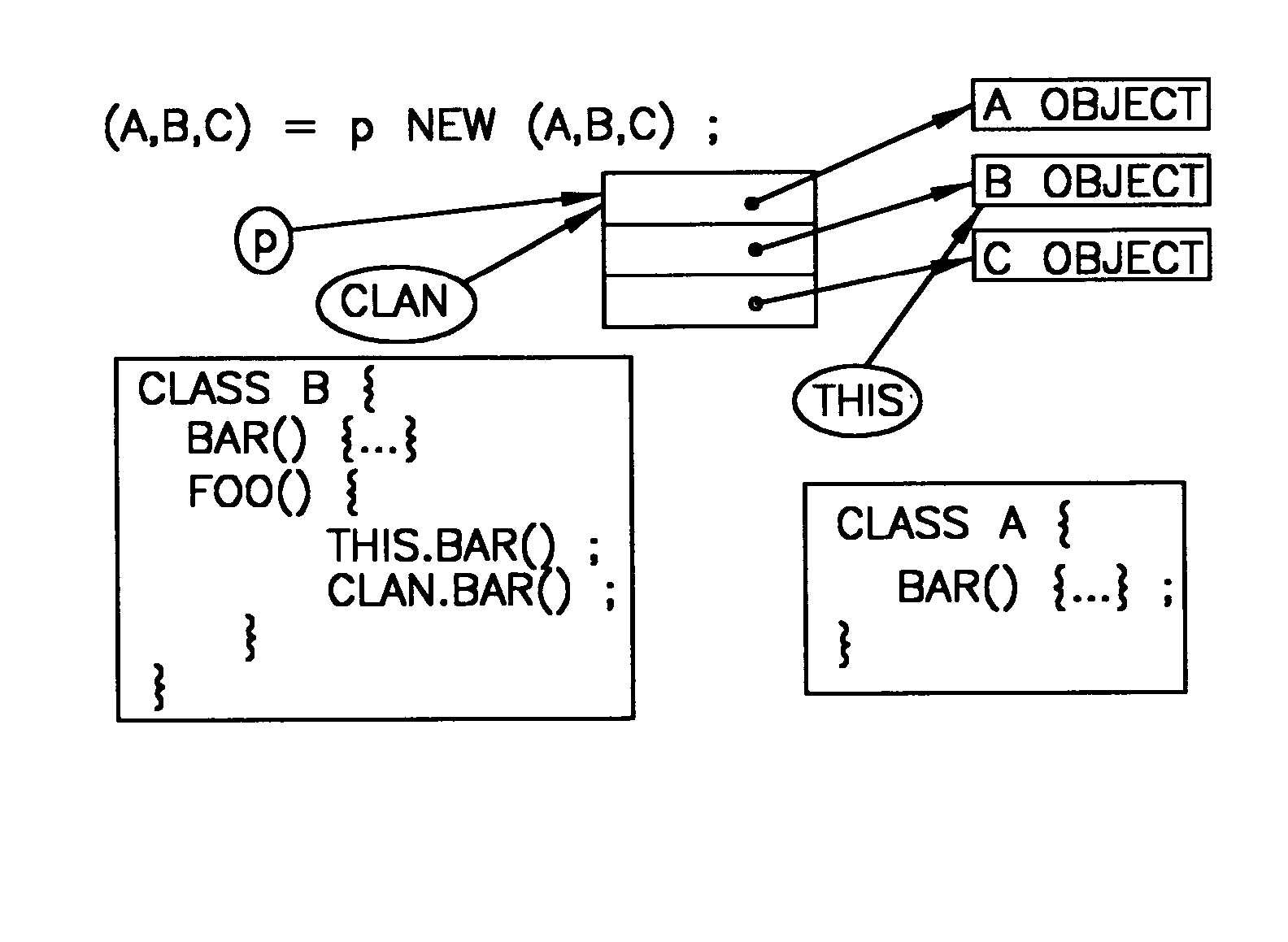
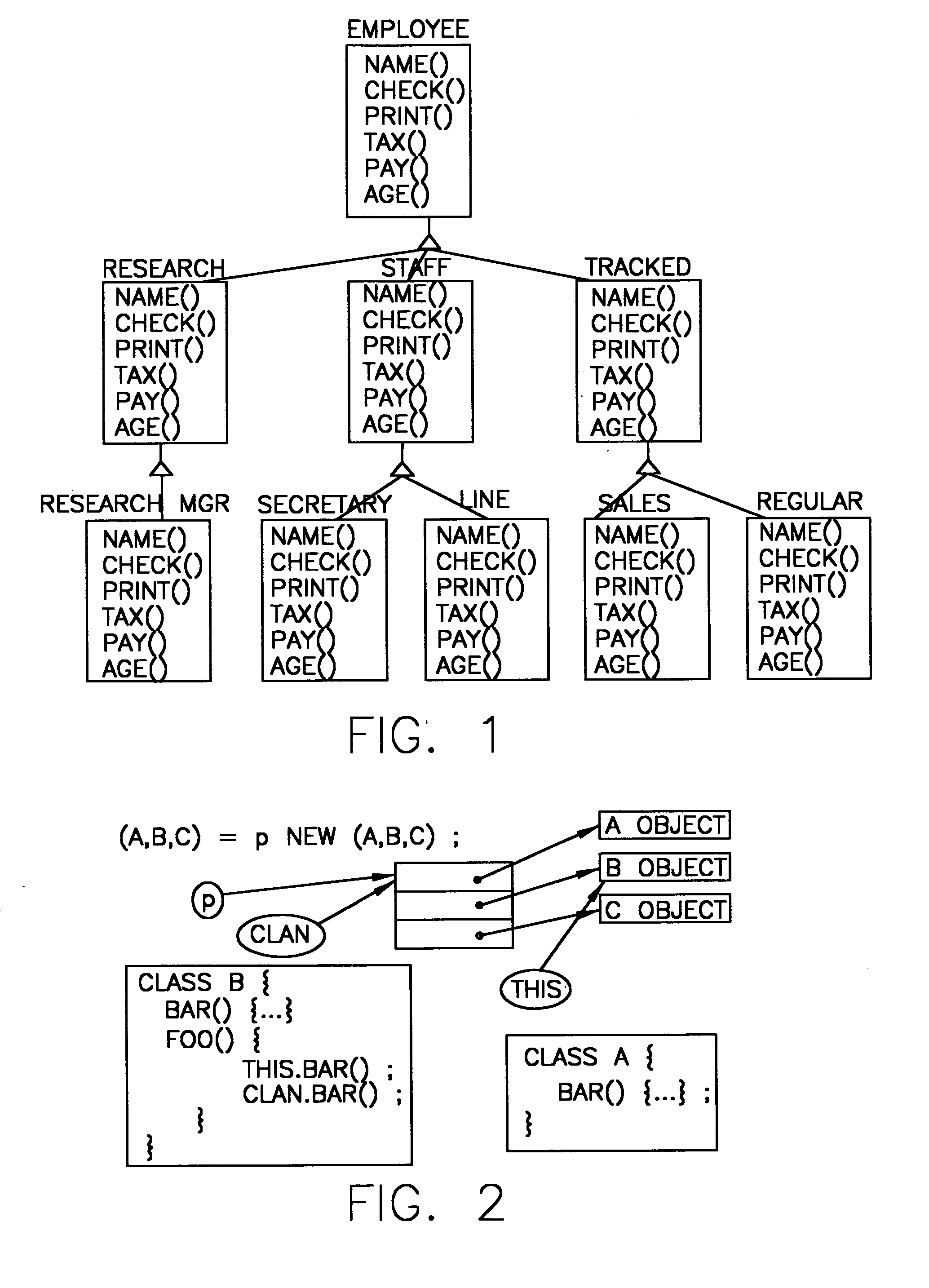
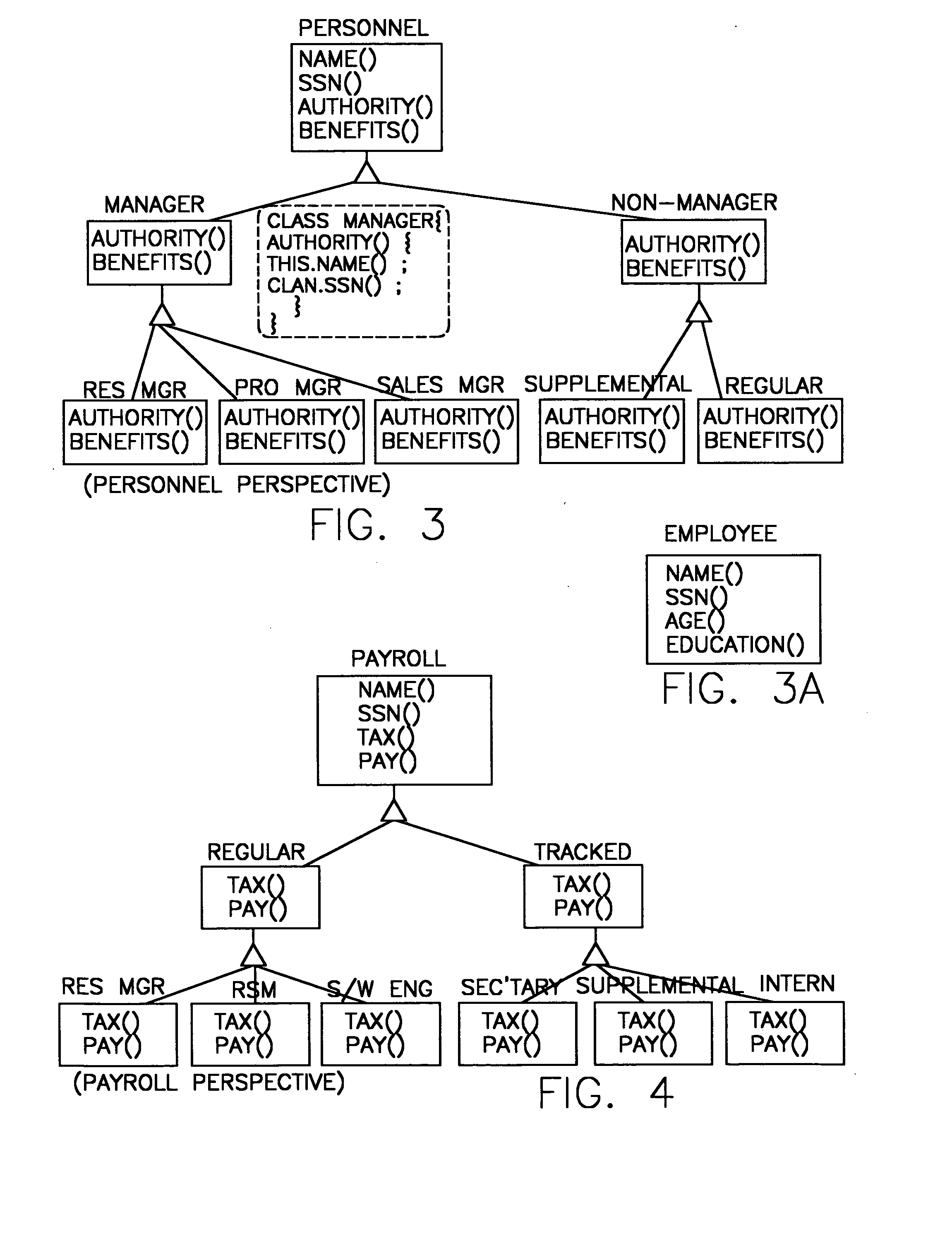
  • Variational modeling using extension types
  • Variational modeling using extension types
  • Variational modeling using extension types

Examples


Embodiment Construction

In connection with developing extension types, one may consider the Decorator pattern. [4] A Decorator pattern allows one to attach additional responsibilities to an object. Consider a Display class that contains a paint( ) method for painting graphical objects. A display object Display d=new Display ( )

can be decorated using DecoratedDisplay class DecoratedDisplay dd=new DecoratedDisplay(d)

DecoratedDisplay is an enhanced Display that contains an enhanced paint( ) method. A call to d.paint( ) is then re-factored to dd.paint( ), to get the effect of the new paint method.

HyperJ (see below) provides a simpler solution for Decorator pattern using a composition rule similar to the following: override(Display, (DecoratedDisplay, Display))

This essentially merges the two classes (the old Display and DecoratedDisplay) into one class. The new class is still called Display and it contains all functionality of the two classes. A method such as paint( ) will be picked up from Decorat...


PUM


Abstract

The use of extension types as a mechanism for an essentially horizontal extension of types for modeling multiple extensions and variations of a software artifact. In that an extension type is a tuple of unrelated classes, each element class in the tuple corresponds to an extension of the extension type. Using extension types, one can bring two unrelated classes or types together to perform computations. Shown herein are manners via which extension types may elegantly model multiple and dynamic extensions of an artifact. Also shown is how extension types simplify aspect-oriented software development and several design patterns.

Description

FIELD OF THE INVENTION The present invention relates generally to the modeling of software artifacts and to various problems and issues encountered in connection therewith. BACKGROUND OF THE INVENTION A list of references is set forth at the close of the present disclosure; individual references from the list are referred to herebelow numerically (i.e., [1], [2], [3], etc . . . ). One of the goals in a free-form interactive surface modeling is to let a user control the shape of the surface design. One way to achieve this is to search for the right representation as controls for direct manipulation by the user. For instance, in control mesh approach, “pushing” or “pulling” a control point makes local “bumps” and “dents” whose shape is relatively easy to control. But local bumps and dents tend not to be the only types of features that a user might want to create. A conceptually simple change can be frustrating since one may have to reposition many, if not all, control points to ach...

Claims


Application Information

Patent Timeline
Patent Type & Authority Applications(United States)
IPC IPC(8): G06F9/44
CPCG06F8/316
Inventor SREEDHAR, VUGRANAM C.
Owner IBM CORP
Learn More