Charged particle beam exposure method of character projection system, charged particle beam exposure device of character projection system, program for use in charged particle beam exposure device, and manufacturing method of semiconductor device

a technology of character projection system and charge beam, applied in the field of charge beam exposure technology, can solve the problems of deteriorating electron beam exposure precision and electron beam exposure accuracy

Inactive Publication Date: 2007-05-24
KK TOSHIBA
View PDF7 Cites 60 Cited by
  • Summary
  • Abstract
  • Description
  • Claims
  • Application Information

AI Technical Summary

Benefits of technology

[0056]FIG. 29 is a schematic diagram of a design data after a dimensional correction processing for the sake of the explanation of a CP allocation in a conventional method;

Problems solved by technology

However, as the wiring patterns are miniaturized, there increases an influence of a dimensional conversion difference on the wiring patterns due to a denseness / coarseness difference of the resist patterns in an etching step of a semiconductor wafer, which leads to a problem that precision of the electron beam exposure deteriorates.
That is, even if the resist pattern can be formed with a dimension faithful to the designed pattern by an electron beam exposure, the denseness / coarseness difference of the resist patterns causes a dimensional difference in the patterns to be formed in an underlayer of the resist pattern, when the underlayer is subjected to an etching process following the patterning of the resist film, with the result that the precision of the electron beam exposure deteriorates.

Method used


Image

  • Charged particle beam exposure method of character projection system, charged particle beam exposure device of character projection system, program for use in charged particle beam exposure device, and manufacturing method of semiconductor device
  • Charged particle beam exposure method of character projection system, charged particle beam exposure device of character projection system, program for use in charged particle beam exposure device, and manufacturing method of semiconductor device
  • Charged particle beam exposure method of character projection system, charged particle beam exposure device of character projection system, program for use in charged particle beam exposure device, and manufacturing method of semiconductor device

Examples


first modification

(First Modification)

[0126] In a first modification of this embodiment, another example of an electron beam exposure method will be described with reference to a data production flow shown in FIG. 32.

[0127] (a) In a step S20, a CP aperture mask 20x shown in FIG. 33 is prepared. In the CP aperture mask 20x, there are arranged a character aperture 70 having opening patterns 70a to 70d all formed into an equal dimension, an opening 80 for VSB, character apertures 71, 72, and 73 having left opening patterns 71a, 72a, and 73a which are differently widened among the opening patterns, apertures 74, 75, and 76 having right opening patterns 74d, 75d, and 76d which are differently widened among the opening patterns, and character apertures 77, 78, and 79 in which opposite end opening patterns 77a, 77d, 78a, 78d, 79a, and 79d are differently widened among the opening patterns. The widened portion amount of each of the opening patterns 72a, 75d, 78a, and 78d is larger than that of each of the o...

second modification

(Second Modification)

[0133] In a second modification of this embodiment, another example of an electron beam exposure method will be described with reference to a data production flow shown in FIG. 37.

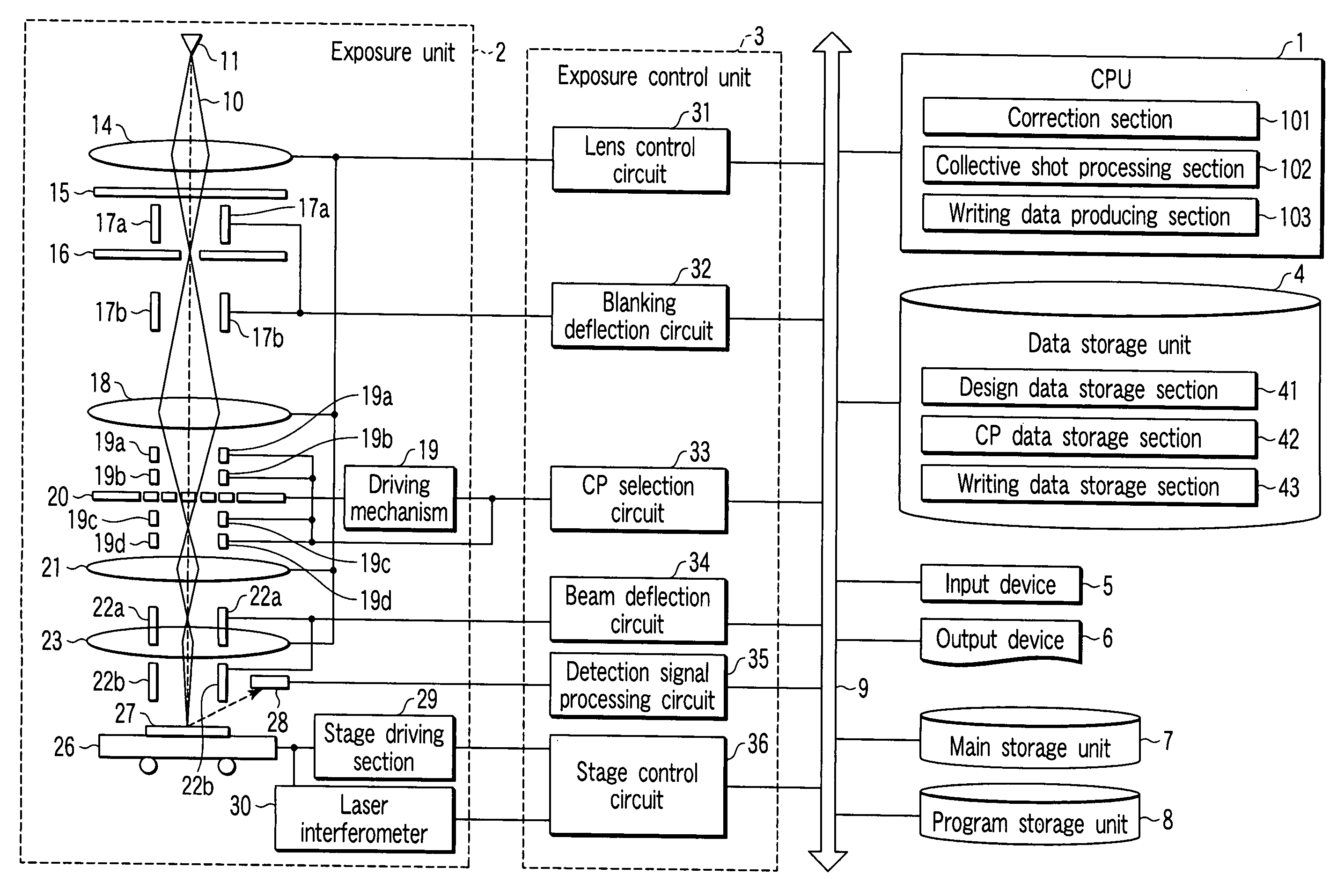
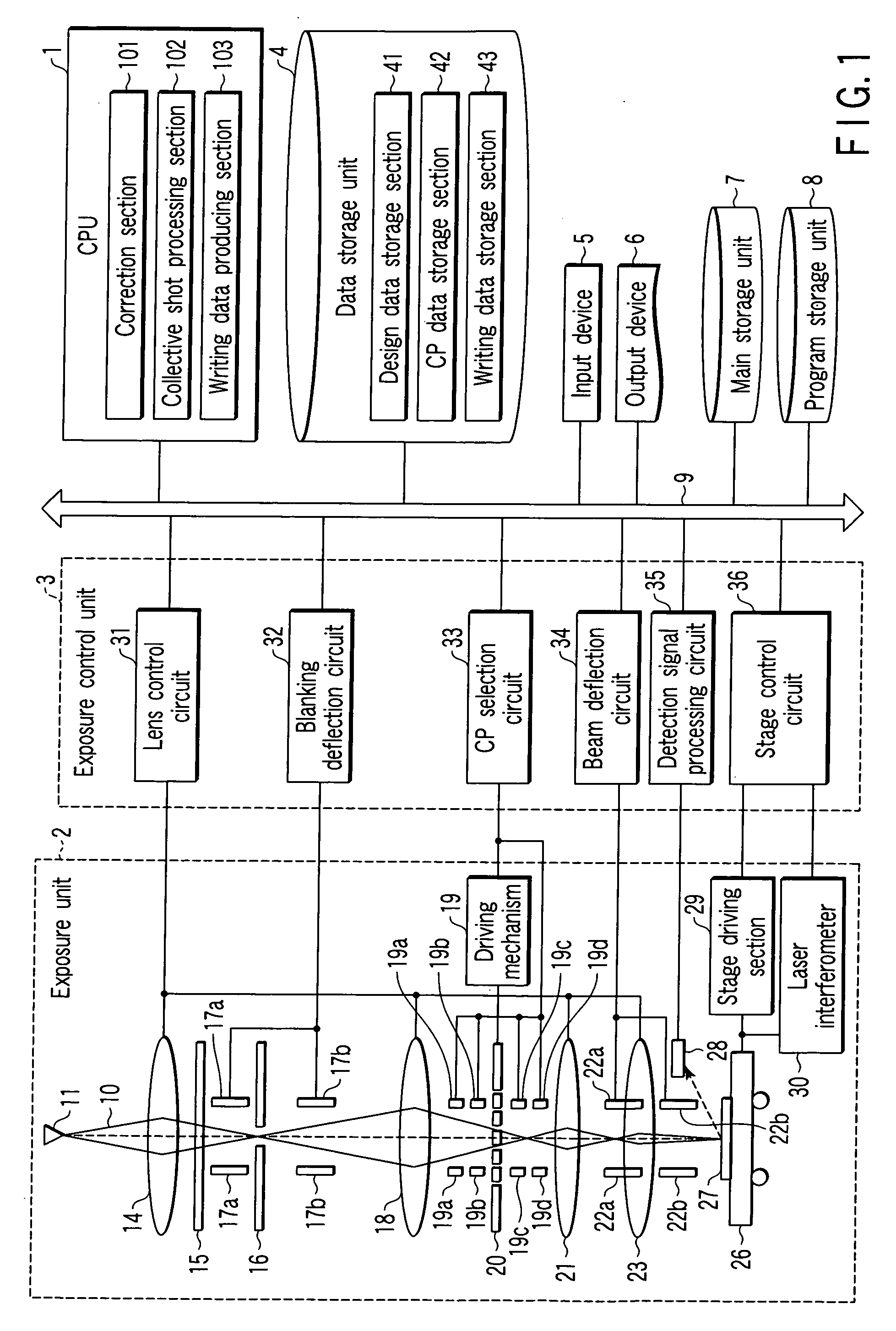
[0134] (a) In a step S30, a CP aperture mask is prepared. In a step S31, the collective shot processing section 102 of the CPU 1 (FIG. 1) performs the collective shot processing with respect to desired LSI design data read from the design data storage section 41. As a result, as shown in, for example, FIG. 38, designed patterns 151a, 151b, 151c, 151d, and 151e are divided into two shot regions A41 and A42.

[0135] (b) In a step S32, the correcting section 101 of the CPU 1 performs the dimensional correction processing with respect to the desired LSI design data read from the design data storage section 41. As a result, the designed pattern 151d having a dimension WL is widened by a dimension ΔWL so that the designed pattern 151d has a dimension WL+ΔWL.

[0136] (c) In a step S33, the wri...


PUM


Abstract

A charged particle beam exposure method is disclosed, which includes preparing an aperture mask having character apertures, correcting dimensions of designed patterns in design data in consideration of at least one of factors such as a forward scattering distance of a charged particle, a rearward scattering distance of the charged particle, a blurring of a beam of the charged particle, a dimension conversion difference of the designed patterns due to a denseness/coarseness difference of the designed patterns caused when the underlayer is processed while using the resist as a mask, and the like, allocating at least a part of a specified character aperture of the plurality of character apertures of the aperture mask to the corrected designed patterns to produce writing data, and exposing the resist to the beams of the charged particle passed through the at least a part of the specified character aperture based on the writing data.

Description

CROSS-REFERENCE TO RELATED APPLICATIONS [0001] This application is based upon and claims the benefit of priority from prior Japanese Patent Application No. 2005-307656, filed Oct. 21, 2005, the entire contents of which are incorporated herein by reference. BACKGROUND OF THE INVENTION [0002] 1. Field of the Invention [0003] The present invention relates to a charged particle beam exposure technology, and more particularly, a charged particle beam exposure method of a character projection (CP) system, a charged particle beam exposure device of the CP system, a program for use in the charged particle beam exposure device, and a manufacturing method of a semiconductor device. [0004] 2. Description of the Related Art [0005] At present, in electron beam exposure, a variably shaped beam (VSB) system is prevalent in which an electron beam is formed into a rectangular shape by use of two aperture masks, and the rectangular electron beam is transferred onto a target object. In recent years, t...

Claims


Application Information

Patent Timeline
Patent Type & Authority Applications(United States)
IPC IPC(8): G21K5/10
CPCB82Y10/00B82Y40/00G03F1/20G03F7/2061H01J37/3174
Inventor NAKASUGI, TETSUROINANAMI, RYOICHIOTA, TAKUMIKOSHIBA, TAKESHI
Owner KK TOSHIBA
Why Eureka
Try Eureka