Particle analyzing apparatus and particle imaging method

a particle analyzing and particle imaging technology, applied in the direction of optical radiation measurement, luminescent dosimeter, instruments, etc., can solve the problem of poor image contras

Inactive Publication Date: 2011-06-02
SYSMEX CORP
View PDF10 Cites 30 Cited by
  • Summary
  • Abstract
  • Description
  • Claims
  • Application Information

AI Technical Summary

Problems solved by technology

The particle measuring apparatus has a problem that its image contrast is poor in the case where the particle to be imaged is an optically transparent particle, for example, a cell.

Method used


Image

  • Particle analyzing apparatus and particle imaging method
  • Particle analyzing apparatus and particle imaging method
  • Particle analyzing apparatus and particle imaging method

Examples


Embodiment Construction

[0032]Hereinafter, a particle analyzing apparatus according to an embodiment of the present invention is described referring to the accompanied drawings. However, the scope of the present invention is not necessarily limited to the particle analyzing apparatus described below.

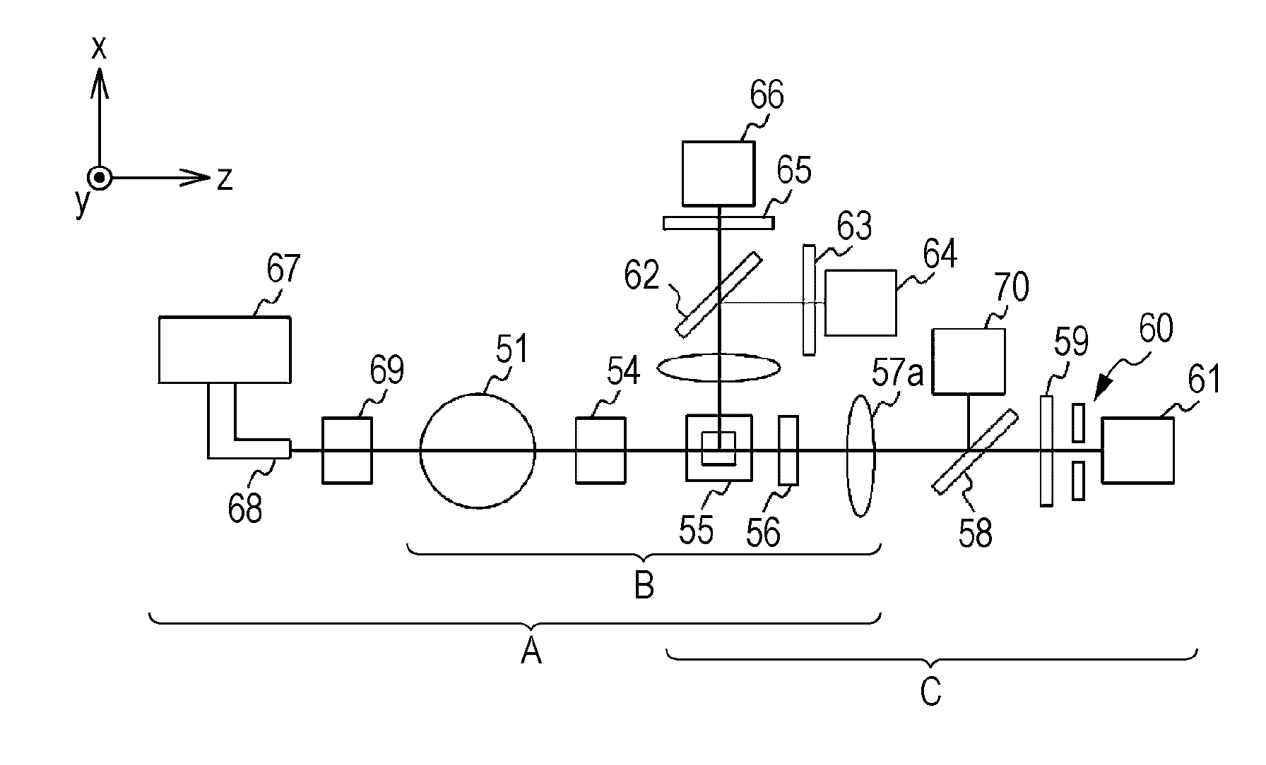
[0033]The particle analyzing apparatus is a cell analyzing apparatus which flows a measurement specimen including cells collected from a patient into a flow cell and applies laser light to the specimen flowing in the flow cell to detect and analyze lights generated from the specimen (for example, forward scattered light, side fluorescent light) to thereby determine whether a cancer cell or an atypical cell (hereinafter, called “abnormal cell”) is included in the cell. More specifically, the cell analyzing apparatus is used in a uterocervical cancer screening test in which epithelial cells are examined.

[Overall Structure of Cell Analyzing Apparatus]

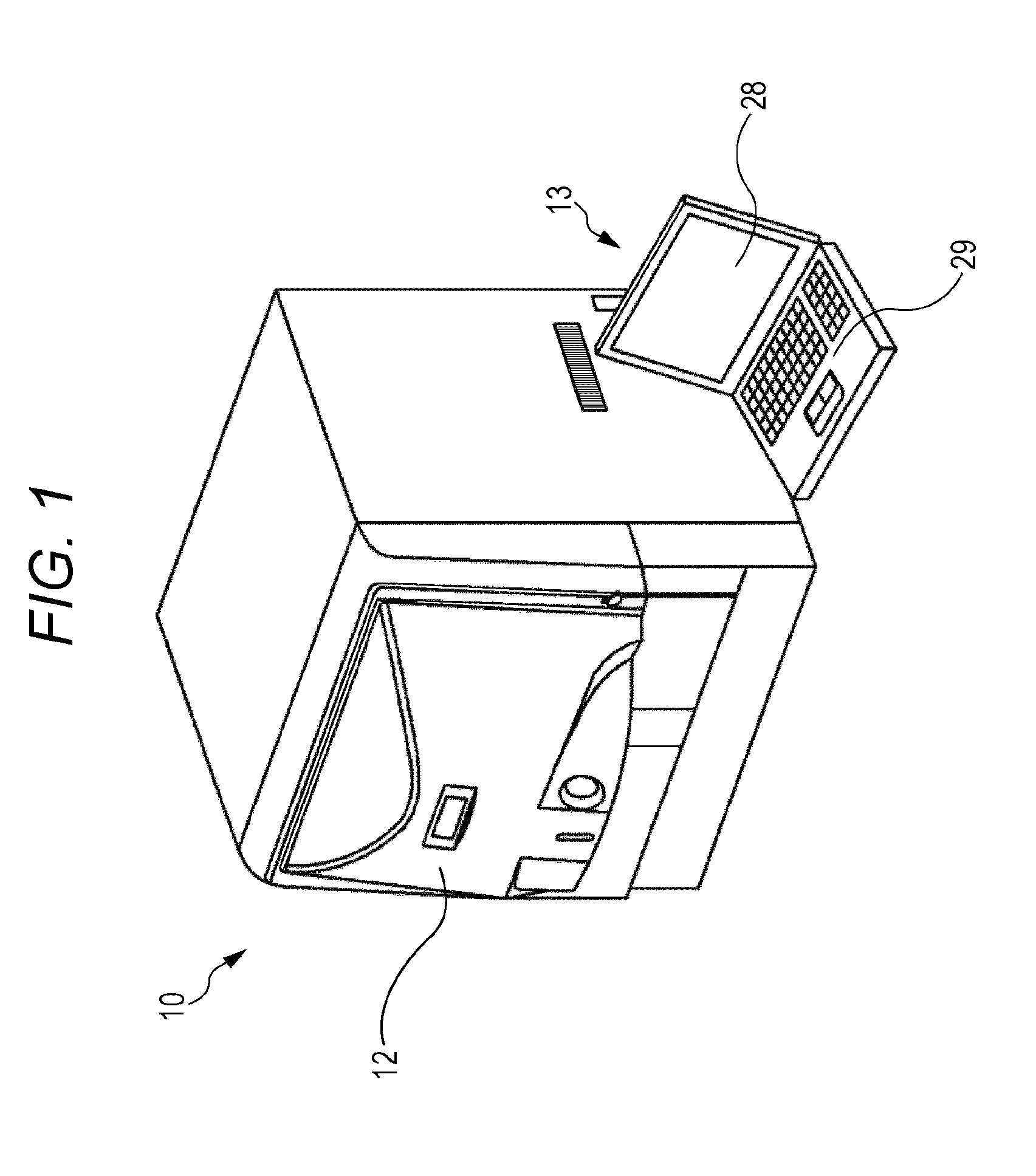
[0034]FIG. 1 is a perspective view of a cell analyzing apparatus...


PUM

PropertyMeasurementUnit
particle imagingaaaaaaaaaa
fluorescent stainingaaaaaaaaaa
particle imaging methodaaaaaaaaaa

Abstract

A particle analyzing apparatus, comprising: a flow cell which forms a specimen flow including particles; first and second light sources; an irradiation optical system which applies lights emitted from the first and second light sources so that the lights are applied to the specimen flow; a detector which detects forward scattered light, the forward scattered light being emitted from the first light and scattered by the particle in the specimen flow, and generates a signal according to the detected scattered light; a light blocking member disposed between the flow cell and the detector; a controller which obtains characteristic parameters of the particle based on the signal from the detector; and an imaging device which captures an image of the particle in the specimen flow using the light from the second light source is disclosed. Particle imaging method is also disclosed.

Description

RELATED APPLICATIONS[0001]This application claims priority under 35 U.S.C. §119 to Japanese Patent Application Nos. 2009-272974 filed on Nov. 30, 2009 and 2010-198593 filed on Sep. 6, 2010, the entire contents of which are hereby incorporated by reference.BACKGROUND OF THE INVENTION[0002]1. Field of the Invention[0003]The present invention relates to a particle analyzing apparatus which applies light to a measurement specimen including particles flowing in a flow cell to analyze the particles using lights generated from the particles in the specimen and particle imaging method.[0004]2. Background Art[0005]The U.S. Pat. No. 6,133,995 discloses a particle measuring apparatus provided with a sheath flow cell which forms a specimen flow including particles enveloped by a sheath liquid, a continuum source and a pulse light source which respectively apply lights to the specimen flow, a detector which detects forward scattered light and fluorescent light generated from the particle on whic...

Claims


Application Information

Patent Timeline
Patent Type & Authority Applications(United States)
IPC IPC(8): G01J1/58G01N15/02
CPCG01N1/31G01N15/147G01N2015/1438G01N2015/0092G01N15/1475
Inventor OZASA, MASATSUGUKOBAYASHI, HIROYUKI
Owner SYSMEX CORP
Why Eureka
Try Eureka