
Forward scattering and transmission combined visibility measuring instrument and measuring method thereof

A forward scattering and visibility technology, used in transmittance measurement, scattering characteristic measurement, etc., can solve the problems of troublesome replacement and cleaning, affect the measurement accuracy of the instrument, and achieve the effect of reducing power drop.

Active Publication Date: 2012-08-15
REMOTE SENSING APPLIED INST CHINESE ACAD OF SCI
View PDF6 Cites 30 Cited by
  • Summary
  • Abstract
  • Description
  • Claims
  • Application Information

AI Technical Summary

Problems solved by technology

From the perspective of the entire visibility measuring instrument, the aging of the instrument's luminescent tube and the contamination of the lens will affect the measurement accuracy of the instrument. Even if the light source and lens can be replaced, it is very troublesome to replace and clean it once.

Method used


Image

  • Forward scattering and transmission combined visibility measuring instrument and measuring method thereof
  • Forward scattering and transmission combined visibility measuring instrument and measuring method thereof
  • Forward scattering and transmission combined visibility measuring instrument and measuring method thereof

Examples


Embodiment Construction

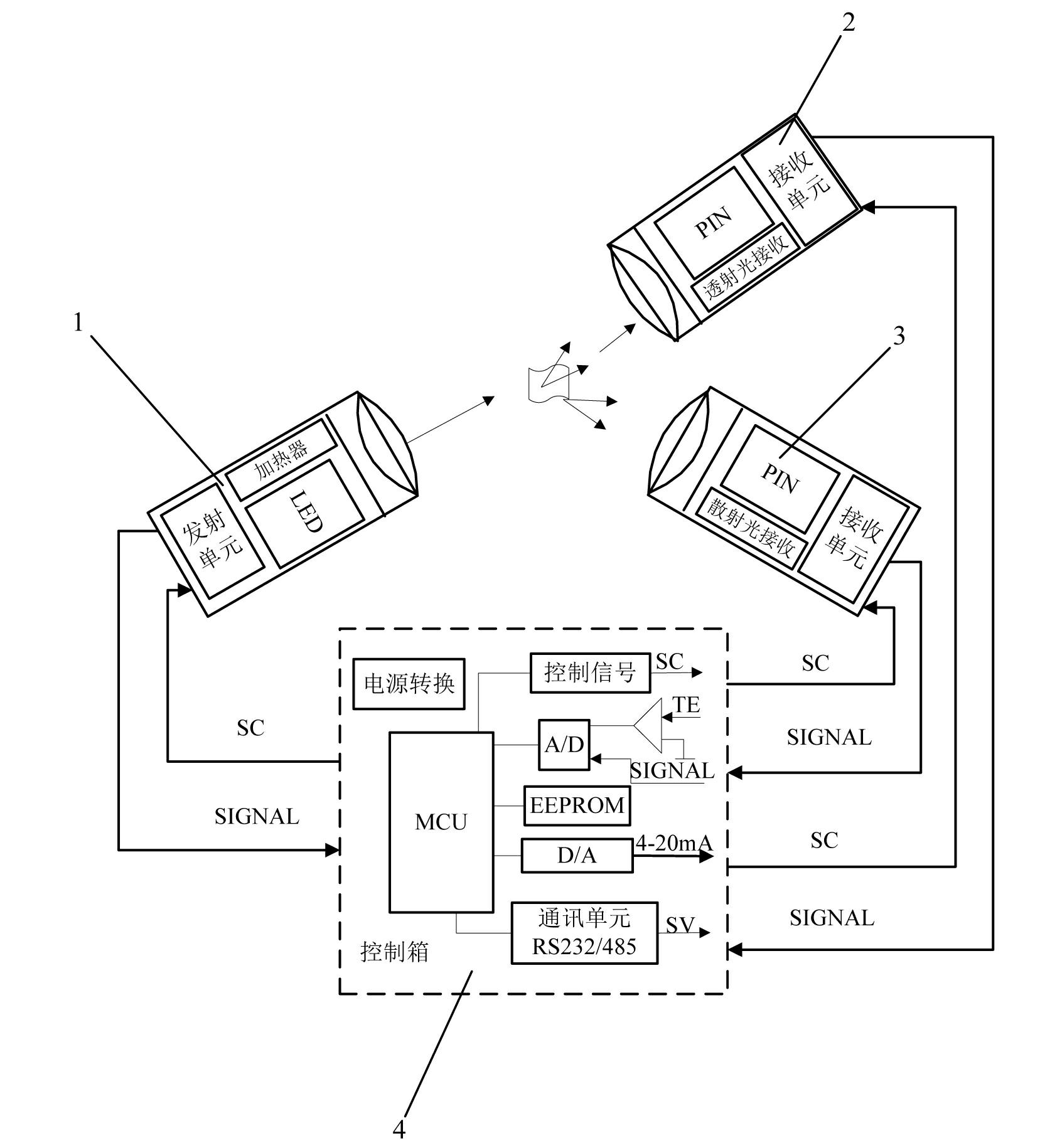
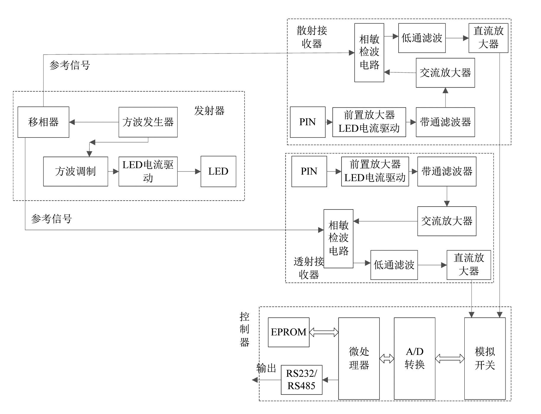
[0017] Such as figure 1 As shown, the visibility measuring instrument combined with forward scattering and transmission of the present invention includes a transmitter 1, a transmission receiver 2, a scattering receiver 3 and a controller 4, and the transmitter 1 is used to transmit to the transmission receiver 2 and the scattering receiver 3 Transmitting optical signals; the transmission receiver 2 is used to receive the optical signal from the transmitter 1 and convert the optical signal into an electrical signal; the scattering receiver 3 is used to receive the optical signal from the transmitter 1 and convert the optical signal converted into electrical signals; the controller 4 is used to receive the electrical signals from the transmission receiver 2 and the scattering receiver 3, and calculate the visibility according to the two electrical signals.

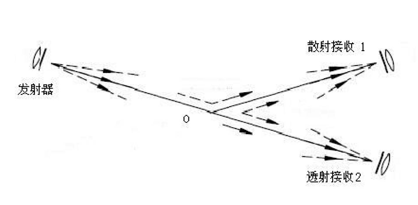
[0018] Such as figure 2 As shown, the optical axes of the transmitter 1, the transmission receiver 2 and the scattering...


PUM

PropertyMeasurementUnit
angleaaaaaaaaaa

Abstract

The invention discloses a forward scattering and transmission combined visibility measuring instrument and a measuring method thereof. The forward scattering and transmission combined visibility measuring instrument comprises a transmitter, a transmission receiver, a scattering receiver and a controller, wherein the transmitter is used for transmitting a light signal to the transmission receiver and the scattering receiver; the transmission receiver is used for converting a received optical signal into a transmission electric signal; the scattering receiver is used for converting the received optical signal into an electric signal; and the controller is used for receiving the electric signals sent from the transmission receiver and the scattering receiver and calculating according to the two electric signals to obtain visibility. Comparison measurement is carried out on a scattered signal and a transmission signal to obtain atmospheric extinction coefficient, thus atmospheric visibility is obtained. Measurement of a transmission light is added on the basis of forward scattering measurement, and a transmission measured value is taken as reference and can correct the visibility, so as to reduce pollution of environmental dust to a lens and influence of factors, such as power reduction caused by ageing of a light-emitting diode, to a measuring result of an instrument, thus measurement accuracy of the instrument is improved and a cleaning period of the lens is prolonged.

Description

technical field [0001] The invention relates to a visibility measuring instrument and a measuring method thereof, in particular to a visibility measuring instrument combining forward scattering and transmission and a measuring method thereof. Background technique [0002] Visibility is a very important element in meteorological observation. Its forecast is not only used for weather analysis of meteorological departments, but also used to describe the degree of air pollution, which is a direct reflection of air pollution; with the development of science and technology, various Automatic visibility measuring instruments are constantly being updated. my country's demand for automatic visibility measuring instruments is increasing, especially the rapid development of highway construction and forest fire detection at the present stage. It is of great significance to develop a visibility instrument with high cost performance, small size, light weight, and easy installation and cal...

Claims


Application Information

Patent Timeline
Patent Type & Authority Applications(China)
IPC IPC(8): G01N21/53G01N21/59
Inventor 顾行发陈继平余涛赵云红孟庆岩高海亮
Owner REMOTE SENSING APPLIED INST CHINESE ACAD OF SCI
Learn More