Interlock/exclusion systems for multiple vaporizer anesthesia machines

Active Publication Date: 2005-04-07
DRAGERWERK AG
View PDF15 Cites 16 Cited by
  • Summary
  • Abstract
  • Description
  • Claims
  • Application Information

AI Technical Summary

Benefits of technology

[0016] The second gas flow unit is arranged when opened to cause the second pin to pivot the first and second pivotable bars, whereupon the first end of the first pivot bar causes

Problems solved by technology

With this arrangement it is impossible to switch more than one vaporizer into a gas circuit at any one time.
While the above interlocks/exclusion systems may be generally suita

Method used


Image

  • Interlock/exclusion systems for multiple vaporizer anesthesia machines
  • Interlock/exclusion systems for multiple vaporizer anesthesia machines
  • Interlock/exclusion systems for multiple vaporizer anesthesia machines

Examples


Embodiment Construction

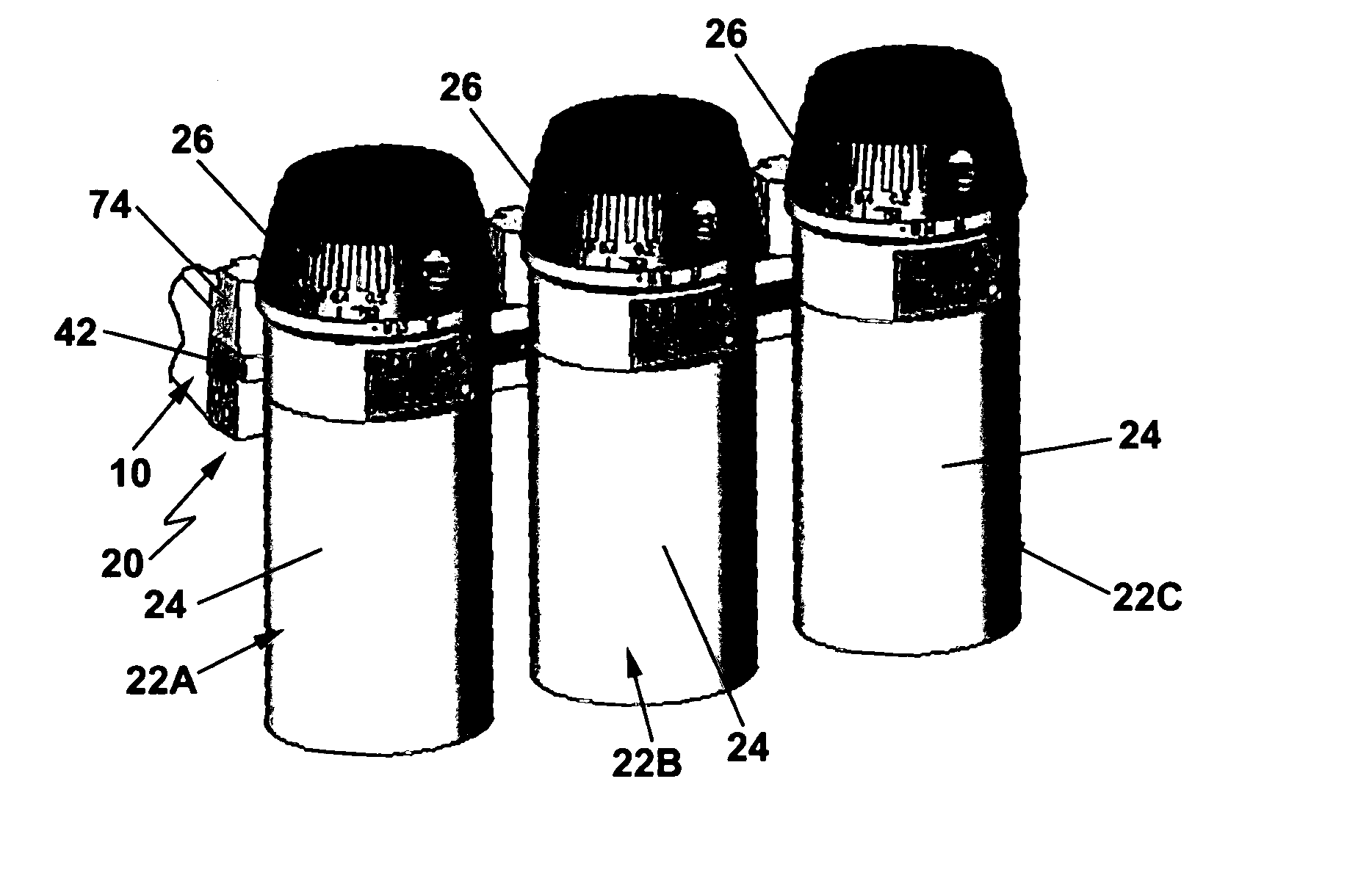
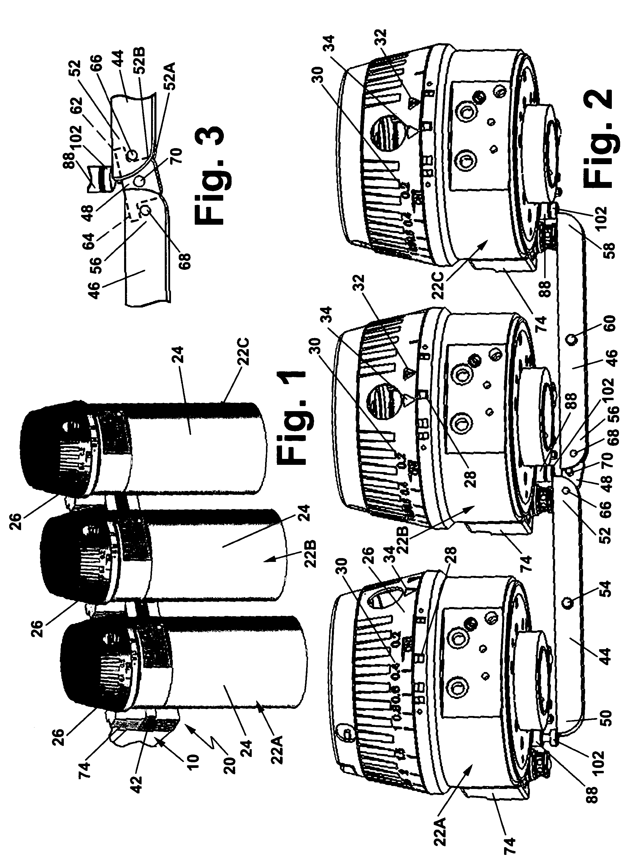
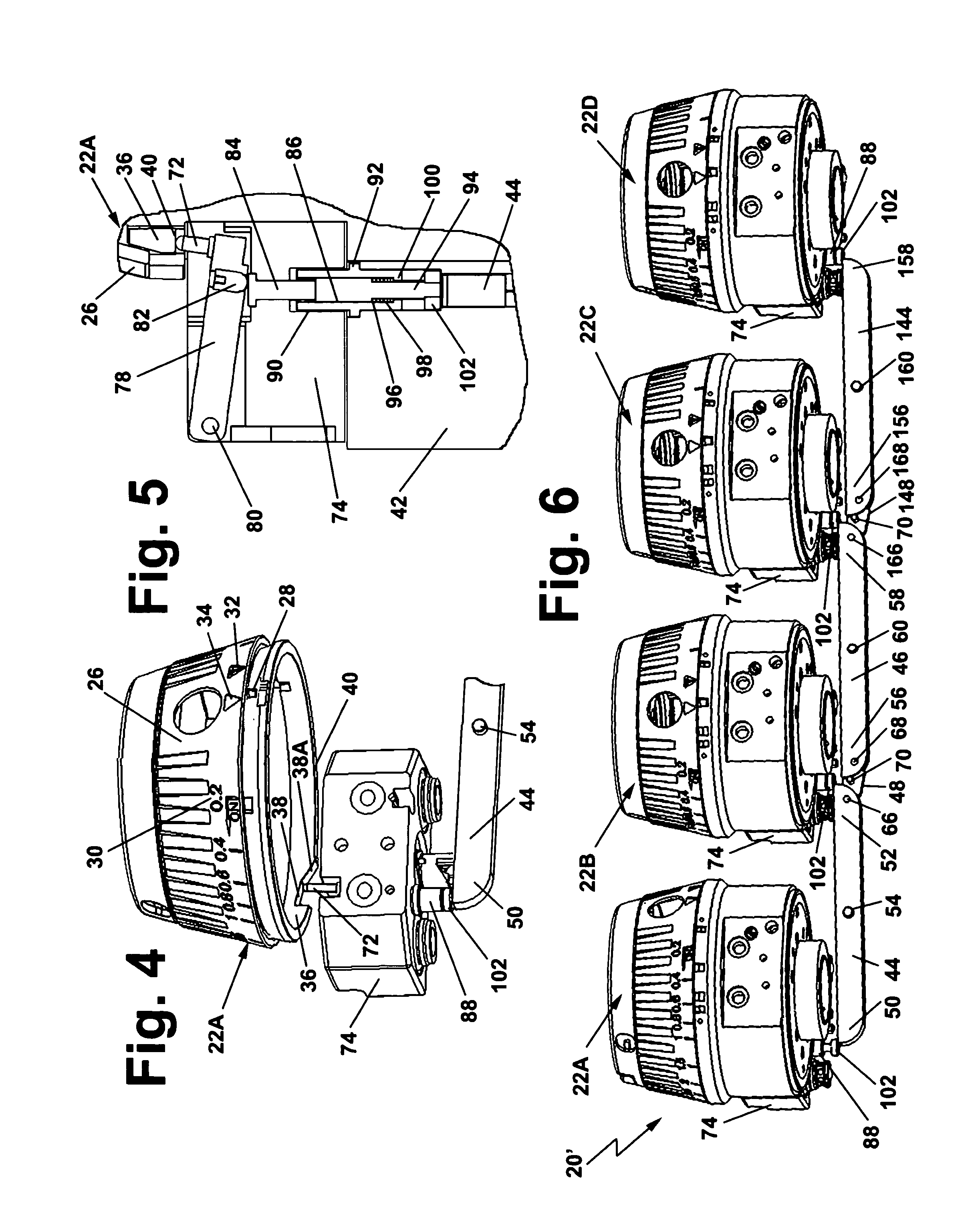
[0025] Referring now to the various figures of the drawing wherein like reference characters refer to like parts, there is shown generally at 20 an interlock / exclusion system for use with an a gas administration apparatus, e.g., anaesthesia machine 10. The machine 10 is configured for use with at least three, removable vaporizers 22A, 22B and and 22C. Each vaporizer is identical in construction, except for the particular anesthesia it is arranged to provide to the machine 10 and is arranged to be releasably mounted on the anesthesia machine in a plug-in fashion. In accordance with one preferred exemplary embodiment of this invention each of the vaporizers is a conventional device, such as that sold under the trademark VAPOR 2000 by Draeger Medical, Inc. of Telford, Pa., the assignee of this invention. The anesthesia machine 10 is also a conventional device, such as that sold under the trademark FABIUS GS by the assignee of this invention, except for the interlock / exclusion system 20...


PUM


Abstract

A gas administration apparatus, e.g., anesthesia machine, making use of three or more gas flow, e.g., vaporizer, units removably mounted thereon by an interlock exclusion system. The interlock/exclusion systems is operative to prevent opening of any gas flow unit if one gas flow unit is already open and irrespective of how many gas flow units are mounted on the apparatus at the time.

Description

BACKGROUND OF THE INVENTION [0001] 1. Field of Invention [0002] This invention relates generally to gas administration apparatus, e.g., anesthesia machines, and more particularly to interlocks or exclusion systems for use with such apparatus having multiple gas flow units, e.g., vaporizers, to prevent more than one gas flow unit from being opened at the same time. [0003] 2. Description of Related Art [0004] It is common practice for an anaesthesia apparatus to have mounted on it two or more separate vaporizers, each arranged for delivering different volatile anaesthetic so that the same basic anaesthesia apparatus can be used during a series of surgical operations to meet the needs of different patients. [0005] In U.S. Pat. No. 4,307,718 (Schreiber), which is assigned to the same assignee as this invention and whose disclosure is incorporated by reference herein, there is disclosed an interlock device for a pair of vaporizers of an anesthesia machine. Each vaporizer includes a rotar...

Claims


Application Information

Patent Timeline
IPC IPC(8): A61M16/10A61M16/18
CPCA61M16/104Y10S261/65A61M16/186
Inventor GERSHTEYN, JACOB
Owner DRAGERWERK AG
Why Eureka
Try Eureka