Wheel clad assembly

a technology of cladding and wheels, applied in the field of composite wheels, can solve the problems of increasing the overall weight of the wheel and the associated cost, and the location of the central aperture of the cladding with respect to the wheel is highly critical, so as to reduce the amount of material required, increase the accuracy of the alignment of the central aperture, and reduce the associated manufacturing cost

Active Publication Date: 2005-04-07
LACKS ENTERPRISES
View PDF10 Cites 32 Cited by
  • Summary
  • Abstract
  • Description
  • Claims
  • Application Information

AI Technical Summary

Benefits of technology

[0010] The present inventive wheel and wheel cladding assembly reduces the amount of material required to construct the wheel, provides increased accuracy of the alignment of the central aperture of the wheel cladding with respect to the wheel, provides proper depth alignment of the wheel cladding with respect to the wheel, and provides proper structural support for the wheel cladding during typical tire-balancing processes. Moreover, the composite wheel and wheel cladding assembly reduce the associated manufacturing costs, can be easy and quickly assembled, are efficient to use, are more economical to manufacture, are capable of a long-operating life, and are particularly well adapted for the proposed use.

Problems solved by technology

However, such designs use a significant amount of material to construct the portion of the wheel surrounding the central hub, thereby increasing the overall weight of the wheel as well as the cost associated therewith.
This arrangement of the wheel, the cladding and the cladding center cap may cause problems when attempting to service the associated vehicle, and specifically when attempting to balance the tires thereof.
As a result, the location of the central aperture of the cladding with respect to the wheel is highly critical.

Method used


Image

  • Wheel clad assembly
  • Wheel clad assembly
  • Wheel clad assembly

Examples


Embodiment Construction

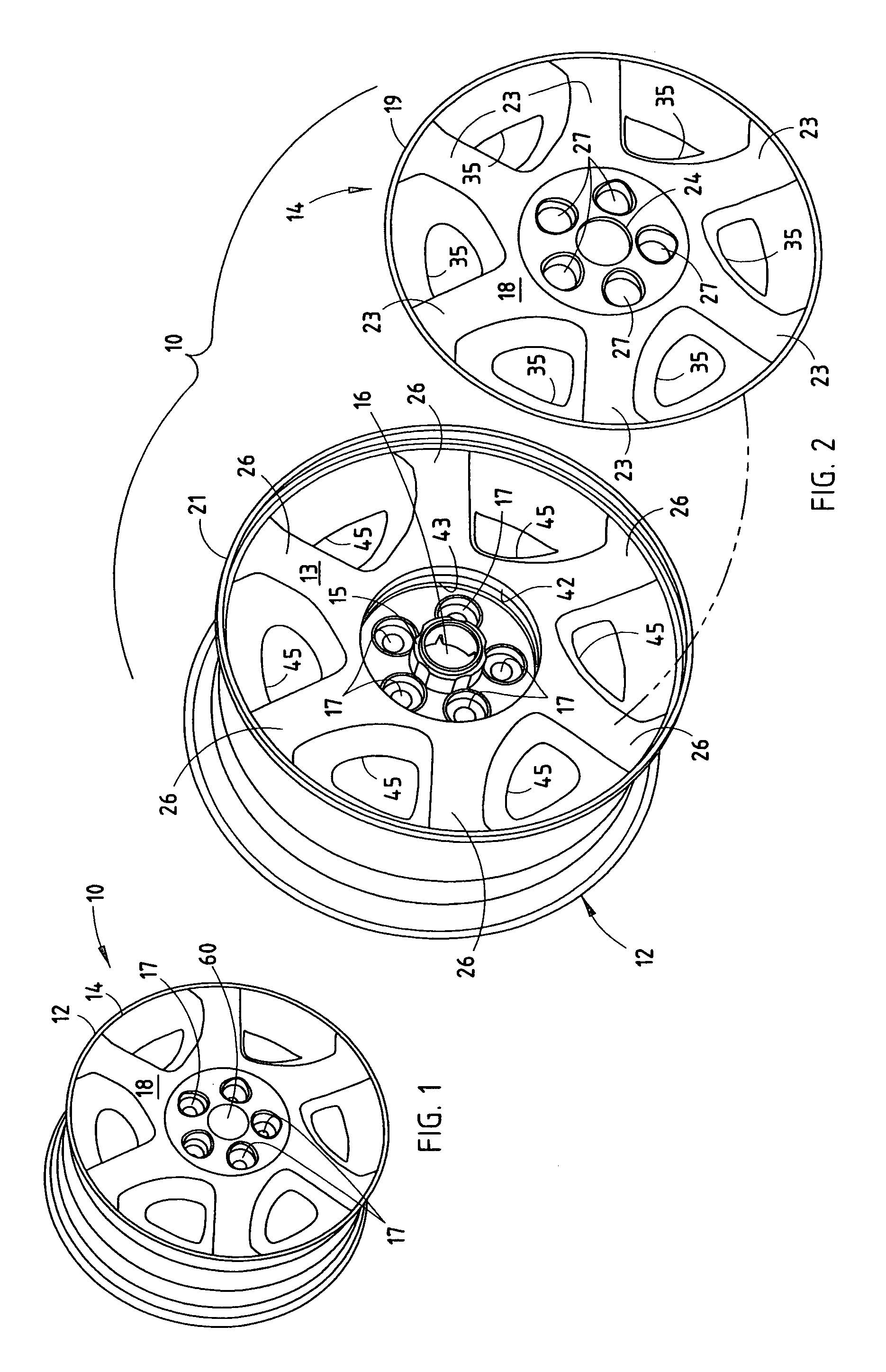
[0020] For purposes of description herein, the terms “upper,”“lower,”“right,”“left,”“rear,”“front,”“vertical,”“horizontal,” and derivatives thereof shall relate to the invention as oriented in FIGS. 1 and 2. However, it is to be understood that the invention may assume various alternative orientations and step sequences, except where expressly specified to the contrary. It is also to be understood that the specific devices and processes illustrated in the attached drawings, and described in the following specification are exemplary embodiments of the inventive concepts defined in the appended claims. Hence, specific dimensions and other physical characteristics relating to the embodiments disclosed herein are not to be considered as limiting, unless the claims expressly state otherwise.

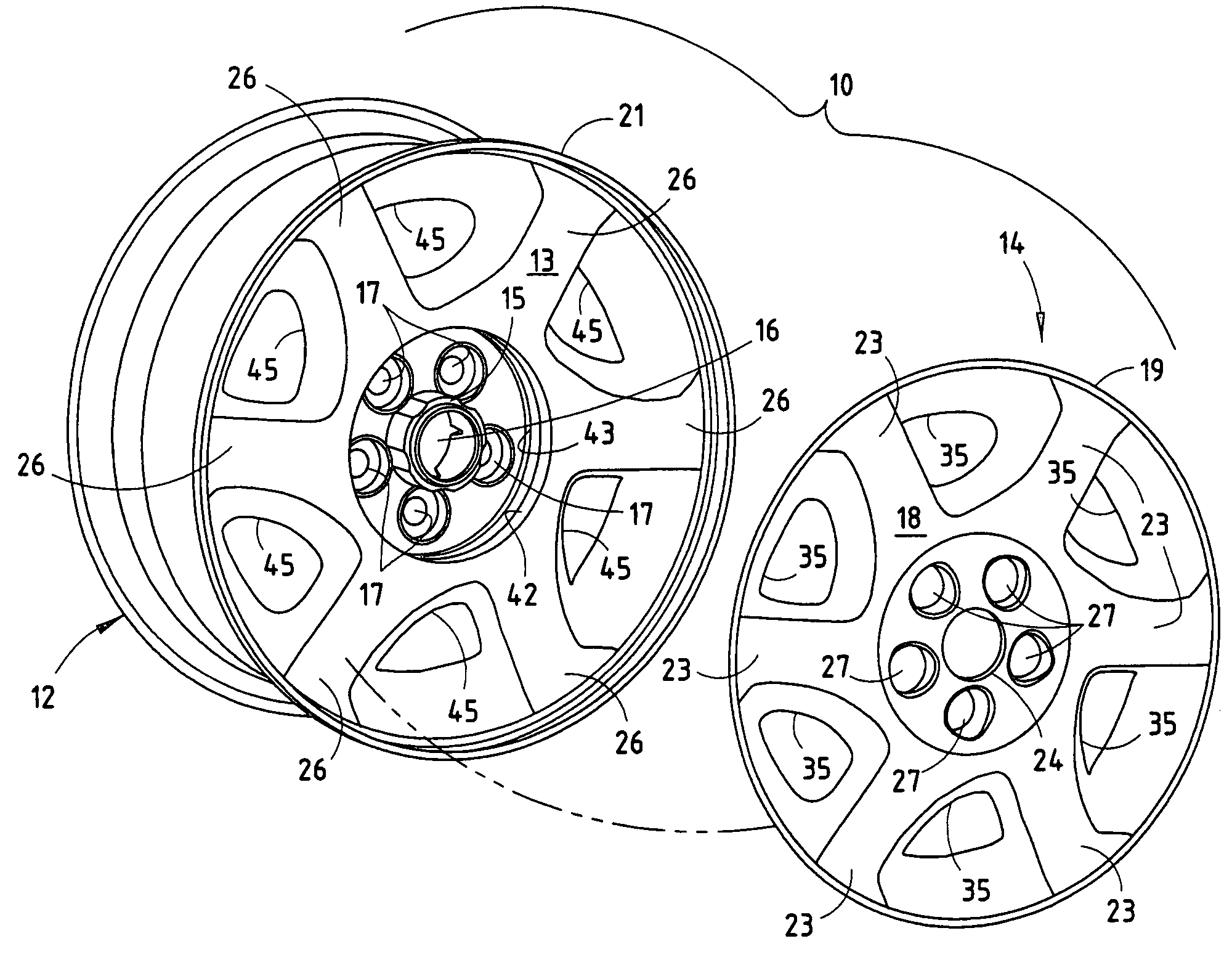
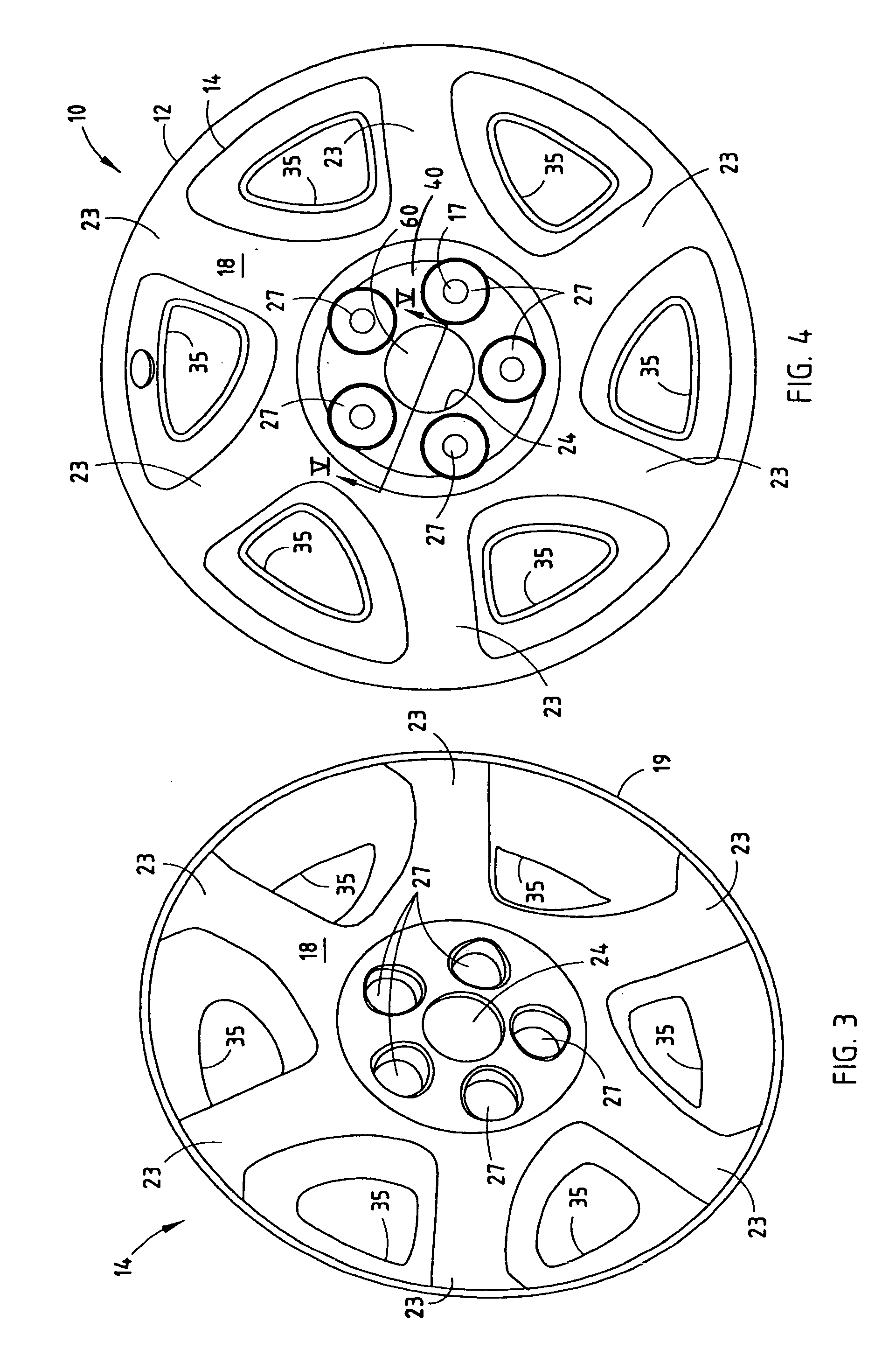
[0021] The reference numeral 10 (FIGS. 1-4) generally designates a composite wheel comprising a wheel 12 made of aluminum, magnesium, steel, or other material conventionally used for manufacturing ve...


PUM


Abstract

A composite wheel that includes a wheel having an outer surface, a plurality of exposed apertures formed in a circular pattern in a central hub region of the wheel, and a centrally-located hub aperture extending through the wheel. The composite wheel also includes a wheel cladding having a body conforming to the outer surface of the wheel, an exposed outer surface, and an inner surface facing the wheel when the wheel cladding is attached to the wheel. The wheel cladding includes at least one alignment tab extending from the inner surface and engaging the hub aperture and aligning the cladding with respect to the hub aperture, and at least one support post extending from the inner surface substantially proximate the hub aperture and structurally supporting the wheel cladding with respect to the wheel.

Description

CROSS REFERENCE TO RELATED APPLICATION [0001] This application claims the benefit of U.S. Provisional Application No. 60 / 420,704, filed Oct. 23, 2003, entitled WHEEL CLAD ASSEMBLY.BACKGROUND OF THE INVENTION [0002] The present invention relates to vehicle wheels, and particularly to a composite wheel including a metal with a polymeric decorative cladding. [0003] Ornamental metal-plated polymeric claddings have been employed for providing a decorative surface to the outer exposed surface of wheels for several years. U.S. Pat. Nos. 5,564,791; 5,577,809; 5,597,213; 5,630,654; 5,636,906; 5,845,973; and 6,085,829, the disclosures of which are incorporated herein by reference, represent different approaches for providing and attaching such claddings to existing wheels to provide a finished decorative appearing wheel. These wheel claddings offer design flexibility in that wheel claddings of various configurations may be used to cover a single style wheel. [0004] Existing methods of attachi...

Claims


Application Information

Patent Timeline
Patent Type & Authority Applications(United States)
IPC IPC(8): B60B5/02B60B7/00B60B7/06
CPCB60B5/02B60B7/0013B60B7/18B60B7/08B60B7/04
Inventor GERARD, PHILIP O.
Owner LACKS ENTERPRISES
Why Eureka
Try Eureka