Integrated coupler

a coupler and integrated technology, applied in the field of couplers, can solve the problems of large filter size, large number of couplers, and bulky couplers, and achieve the effect of easy and accurate setting of values

Active Publication Date: 2005-04-07
STMICROELECTRONICS SRL
View PDF6 Cites 3 Cited by
  • Summary
  • Abstract
  • Description
  • Claims
  • Application Information

AI Technical Summary

Benefits of technology

[0018] The present invention also aims at enabling easy and accurate setting of the values of the coupler components.

Problems solved by technology

Such couplers are bulky due to the size of the lines to be formed, especially for radio frequency applications (from several hundreds of MHz to a few GHz).
A disadvantage of passive couplers with local components such as that illustrated in FIG. 2 is linked to the dispersions (on the order of 20%) of the inductive and capacitive components upon manufacturing thereof.
However, the required number of stages (filter order) results, in practice, in a large size filter.
Further, the dispersion problem is also present for resistors.

Method used


Image

  • Integrated coupler
  • Integrated coupler
  • Integrated coupler

Examples


Embodiment Construction

[0028] The same elements have been designated with the same reference numerals in the different drawings. For clarity, only those components which are necessary to the understanding of the present invention have been shown in the drawings and will be described hereafter. In particular, the exploitation that is made of the measurements performed by a coupler according to the present invention has not been described in detail, the present invention applying whatever the type of measurements performed and whatever the transmit line on which the coupler is connected.

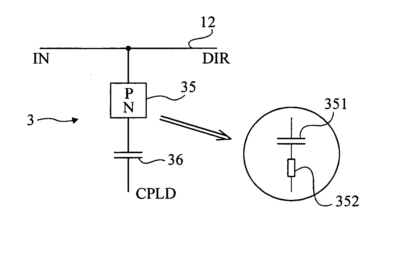
[0029] A feature of the present invention is to form an integrated coupler in the form of a semiconductor junction (PN) in series with a capacitor.

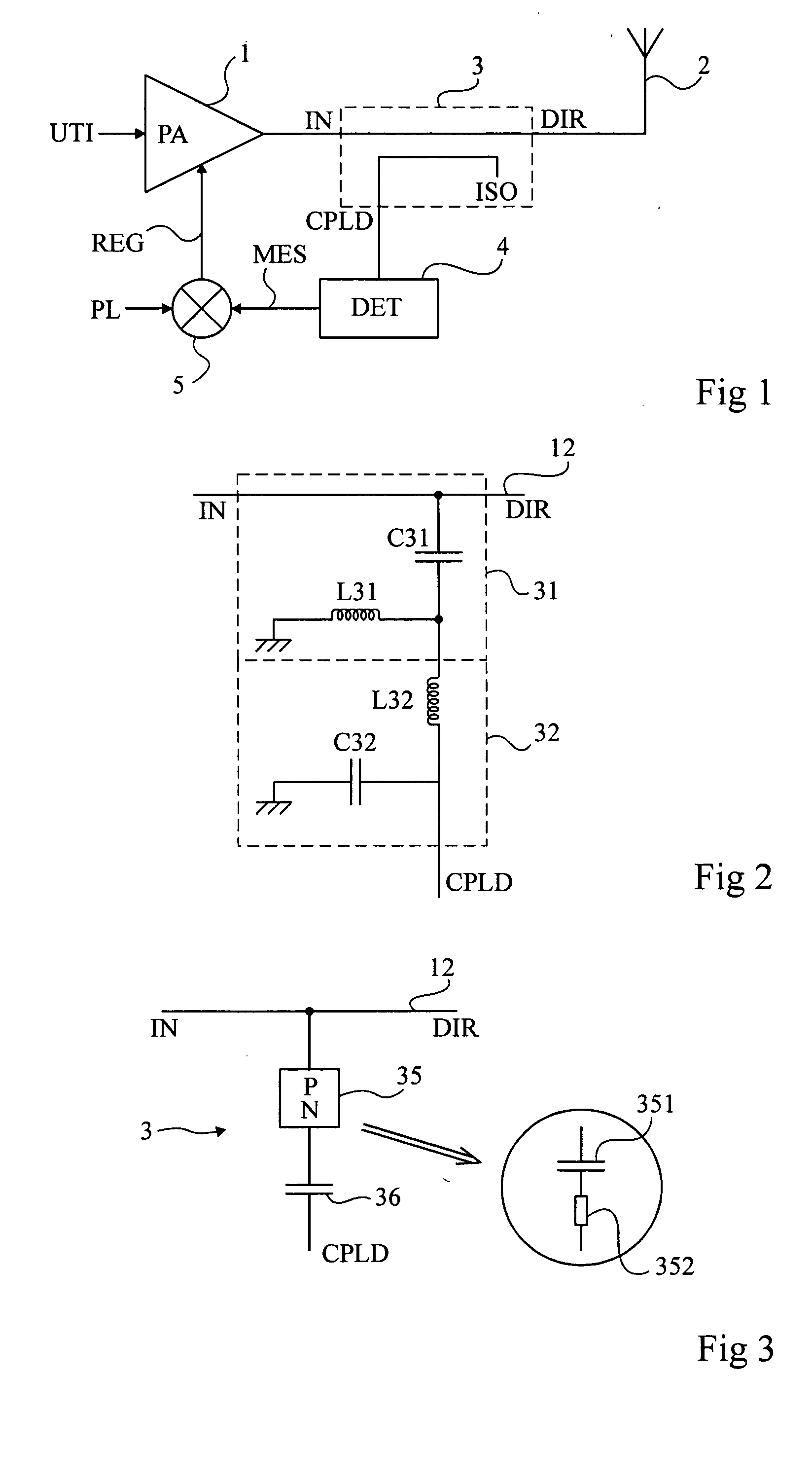
[0030]FIG. 3 shows an embodiment of a coupler 3 according to the present invention.

[0031] A PN junction 35 is connected by a first terminal (indifferently P or N) to transmit line 12 (confounded terminals IN and DIR) while its other terminal is connected to a first electrode of...


PUM


Abstract

A non-directional coupler including a semiconductor junction in series with a capacitor, the semiconductor junction being formed so that the threshold frequency short of which it behaves as a rectifier is smaller than the coupler's operating frequency.

Description

BACKGROUND OF THE INVENTION [0001] 1. Field of the Invention [0002] The present invention relates to the field of couplers having the function of sampling part of the power present on a main line towards a secondary line for control and feedback. Couplers are generally used in closed-loop gain-control systems to provide a real measurement of the power. [0003] 2. Discussion of the Related Art [0004]FIG. 1 very schematically shows an example of a conventional circuit using a coupler. This example relates to the control of a power amplifier 1 (PA) for amplifying a useful signal UTI for a transmit antenna 2. In this type of application, the transmit power is controlled with a power reference PL. A coupler 3 is interposed between the output of amplifier 1 and antenna 2 to extract data proportional to the power actually transmitted. This data is exploited by a detector 4 (DET) providing a measured value MES to a comparator 5 with required power PL. Comparator 5 provides a control signal R...

Claims


Application Information

Patent Timeline
Patent Type & Authority Applications(United States)
IPC IPC(8): H01L27/04H01L21/822H03H7/48
CPCH03H7/487
Inventor DUPONT, FRANCOISPOVEDA, PATRICK
Owner STMICROELECTRONICS SRL
Why Eureka
Try Eureka